Difference between revisions of "Betsy Bertha's m-TDI"
m (→EGT Probe) |
|||
| (173 intermediate revisions by 2 users not shown) | |||
| Line 2: | Line 2: | ||
|title=Betsy Bertha's mTDI AHU Conversion | |title=Betsy Bertha's mTDI AHU Conversion | ||
|titlemode=append | |titlemode=append | ||
| − | |keywords=VW,Vanagon,TDI,diesel,conversion,T3,T25,Westfalia,Westy | + | |keywords=TDI Vanagon,VW,Vanagon,TDI,diesel,conversion,T3,T25,Westfalia,Westy,mTDI Conversion,vanagon diesel conversion, diesel vanagon conversion |
| − | |description=Betsy's | + | |description=Betsy's mTDI AHU Conversion Page |
}} | }} | ||
| − | == | + | == Version == |
| − | + | === 1.4 === | |
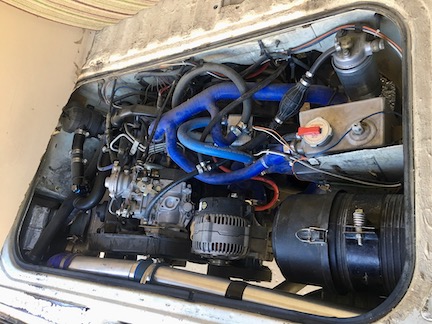
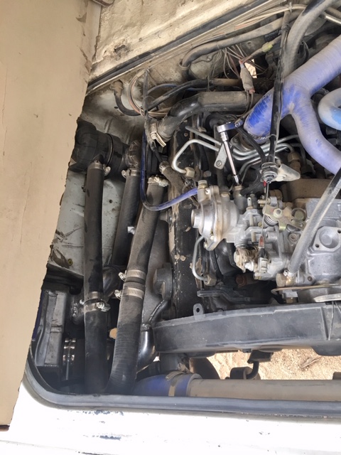
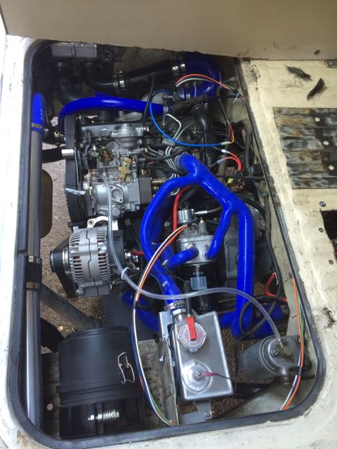
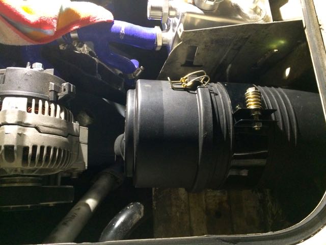
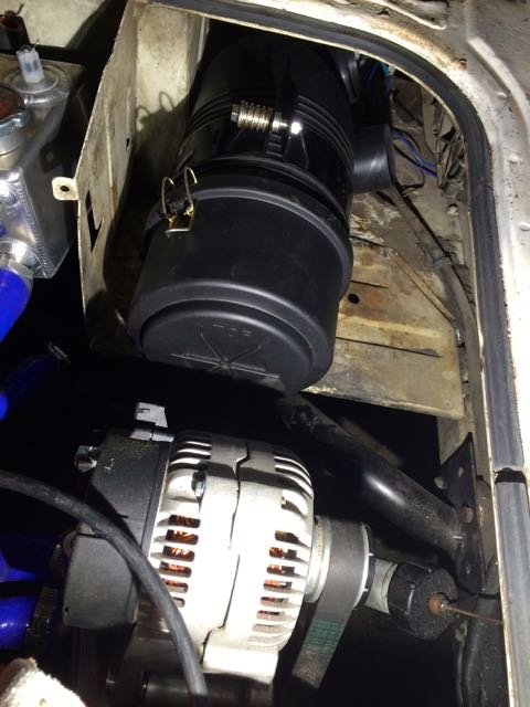
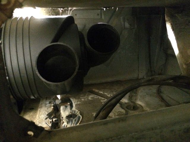
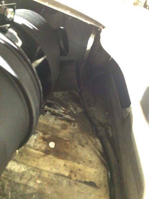
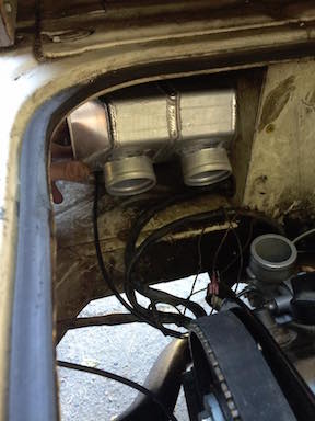
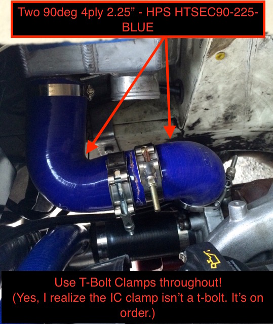
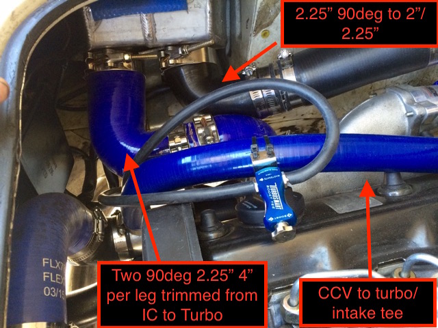
| − | This | + | :*Larger 3” Donaldson installed. It’s filter supports 215cfm. I also went 3” to 2.25” all way to turbo—turbo inlet is 2.25” |
| + | |||
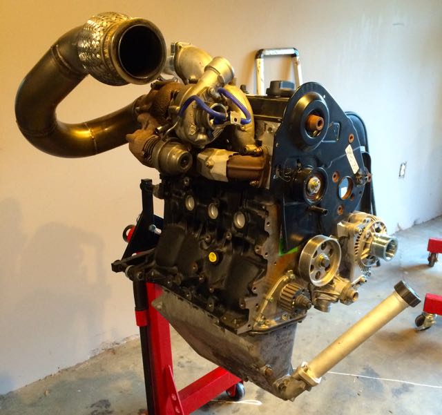
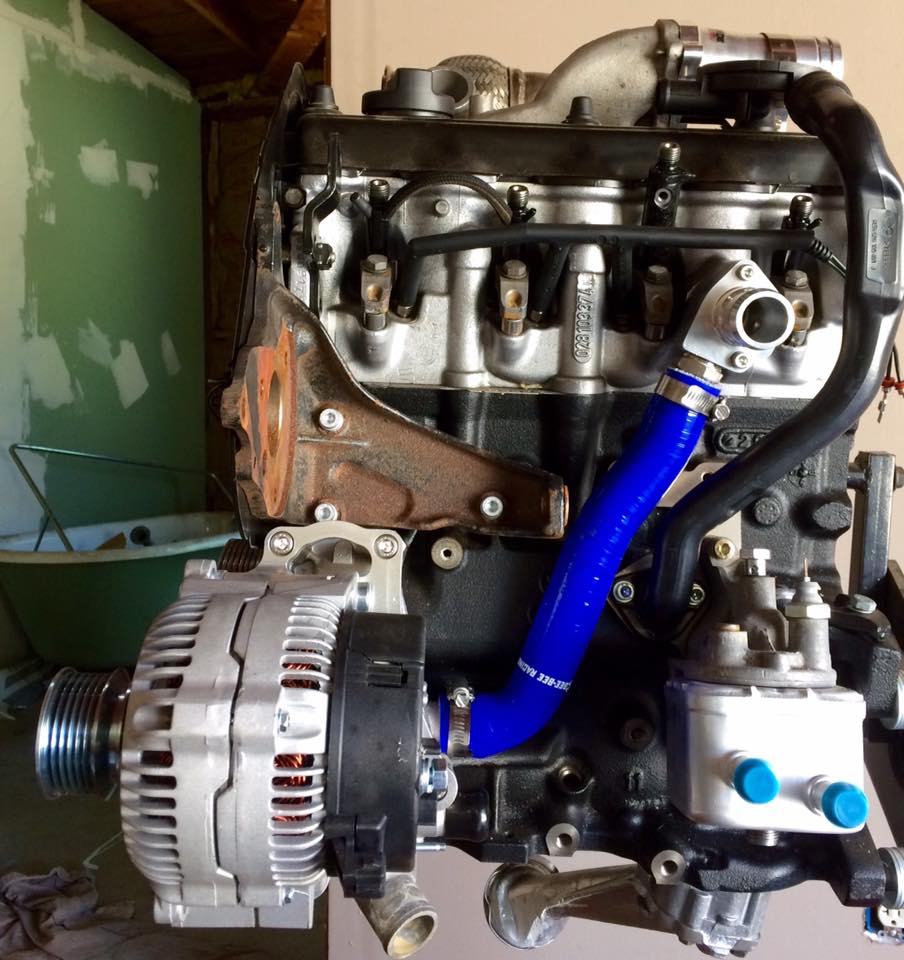
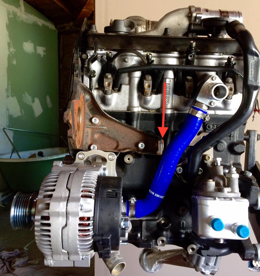
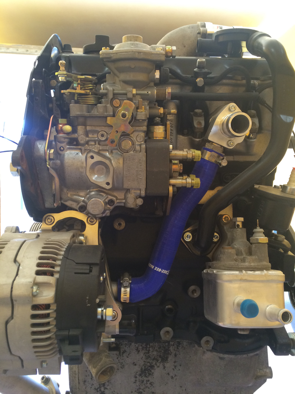
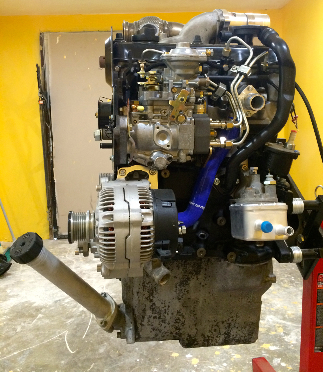
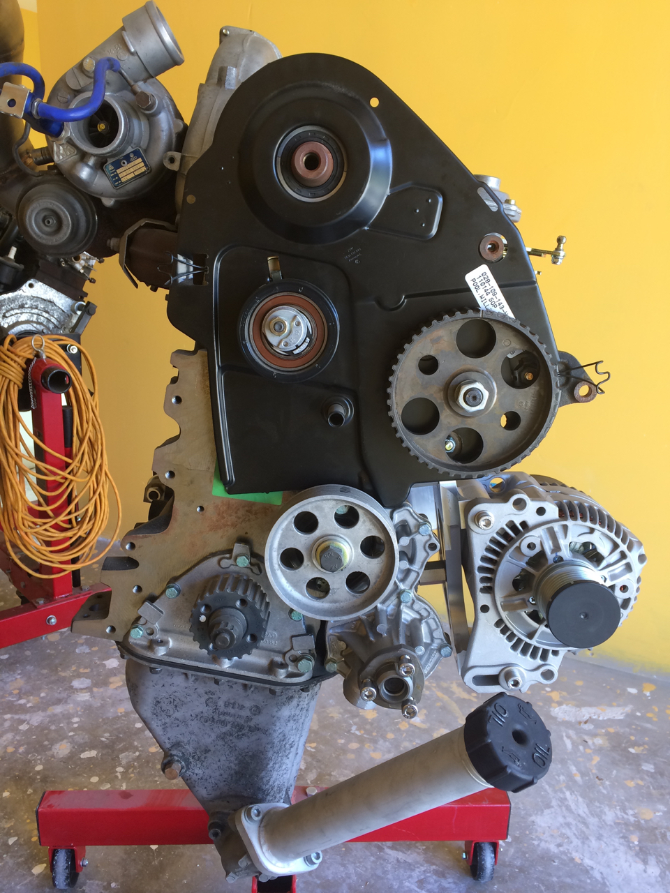
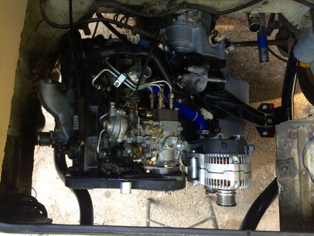
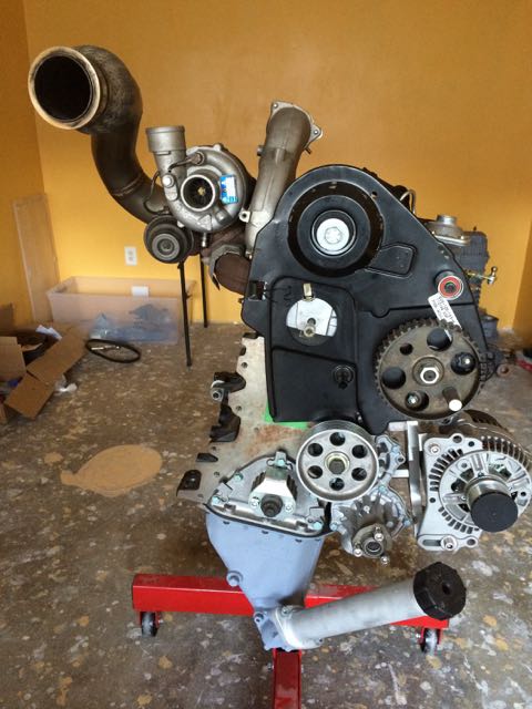
| + | [[File:Betsy-rev4.jpg]] | ||
| + | |||
| + | === 1.3 === | ||
| + | |||
| + | :*76k miles on conversion 11/19 | ||
| + | |||
| + | '''Upgrades:''' | ||
| + | |||
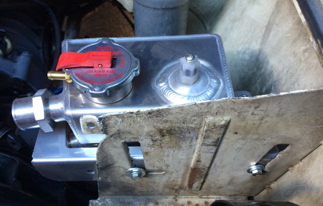
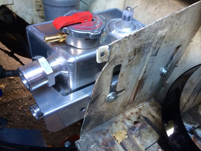
| + | :*GT2052 Turbo - This is requiring me to upgrade my [http://www.vanagondiesel.info/index.php/Cooling_System Airbox Setup] | ||
| + | :*Custom Intake Manifold that better positions to the IC and flows better | ||
| + | :*Mann Provent 200 catch-can - was required with boosting past 18psi | ||
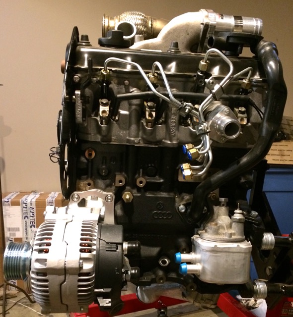
| − | + | [[File:Betsy-Rev3a.jpg]] | |
| − | + | [[File:Betsy-Rev3b.jpg]] | |
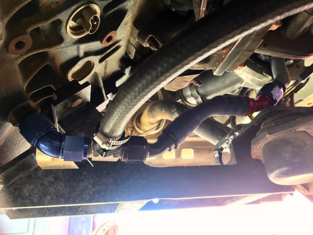
| − | + | Here is a photo of the new drain layout with the GT2052 | |
| − | + | [[File:Betsy-Rev3c.jpg]] | |
| − | + | With the updated Mann Provent 200 the 90deg off the CCV puck still had too much pressure. A 180deg that extended to the end of the head took care of the seepage at the puck! | |
| − | + | [[File:Betsy-Rev3d.jpg]] | |
| − | + | === 1.2 === | |
| − | + | :* 62K miles on conversion 05/19 | |
| − | I | + | Hauling a lot of weight my oil temps can get up high. I installed the 2.0 TDI Oil Cooler with Karl's moddification, and it's WAY better oil-temps. |
| + | p/n: 038117021B | ||
| − | + | [[File:PD130TDI OC.jpg]] | |
| − | + | === 1.1 === | |
| − | + | :* 45k miles on conversion 08/18 | |
| − | + | :* IC T-bolt clamps get loose, the nylon locnuts vibrate and loosen with pressure. Use metal lock washers and metal pressure nut and use red loctite. | |
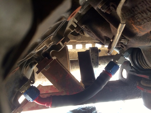
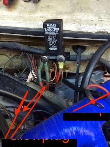
| − | + | :* Insulate Oil Feed Line near the Glow Plug relay. Avoid a fire! | |
| − | + | :* Install a boat hand fuel priming bulb at fuel filter line to IP to help prime | |
| − | + | [[File:Betsy34k.JPG]] | |
| − | + | === 1.0 === | |
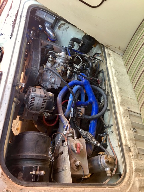
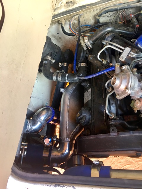
| − | + | First run! | |
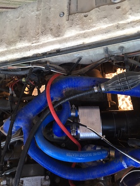
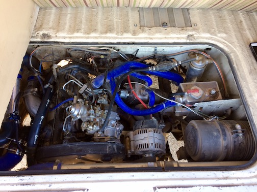
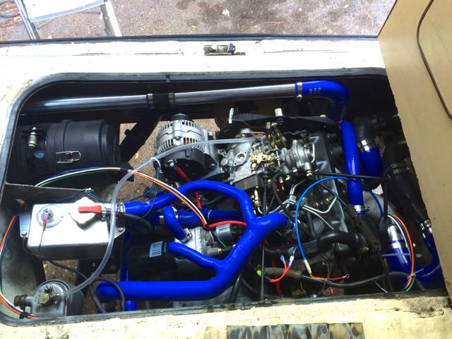
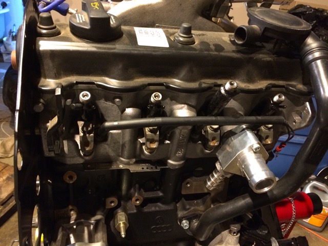
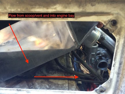
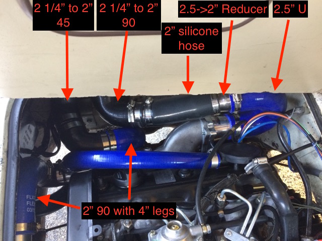
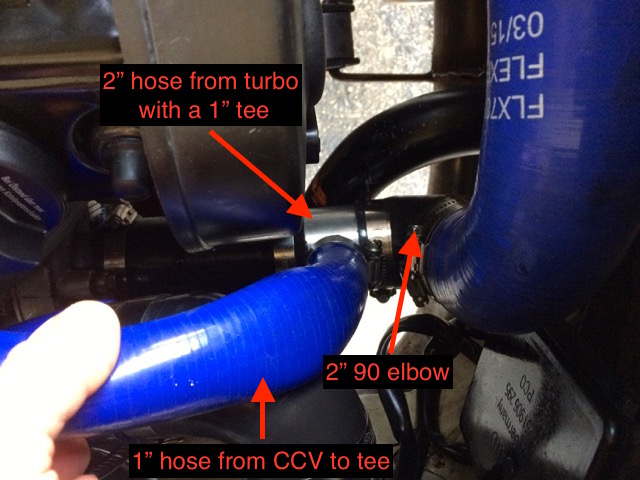
| − | + | [[File:IC Intake Routing.jpg]] | |
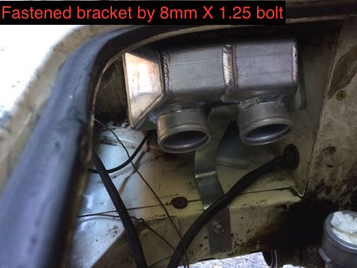
| − | + | [[File:IC Intake Routing 2.jpg]] | |
| − | + | == Caution == | |
| − | + | Unless you follow this build to the tee using all the same hardware, your milage may vary; YMMV. | |
| − | + | Always document what you DO even if you follow this! | |
| − | + | Label all wires, take photos, or videos. When you remove stuff from the old engine, do the same. If you're diligent with that and follow this; you'll do fine. | |
| − | + | This tutorial is based off of a 1z/AHU engine. Other engines, YMMV! | |
| − | + | === Vanagon specific Vendors === | |
| − | [http://van-cafe.com | + | [http://rockymountainwesty.com Rocky Mountain Westy] & [http://van-cafe.com Van-Cafe] are the same company now. |
| − | [http:// | + | [http://t3technique.com T3Technique] |
| + | |||
| + | [http://westyventures.com WestyVentures] | ||
=== Why mTDI and not a normal TDI? === | === Why mTDI and not a normal TDI? === | ||
| Line 80: | Line 95: | ||
These can all be argued, but it's the direction I went. | These can all be argued, but it's the direction I went. | ||
| − | So, what *IS* a mTDI? A mTDI is essentially a TDI engine (1z/AHU/AFN ideally if at 50 degrees) with a mechanical pump instead of an electrical pump. Think of it as an AAZ with all the TDI goodness. | + | So, what *IS* a mTDI? A mTDI is essentially a TDI engine (1z/AHU/AFN ideally if at 50 degrees) with a mechanical pump instead of an electrical pump. Think of it as an AAZ with all the TDI goodness. |
| + | |||
| + | My last comment about the [https://www.youtube.com/watch?v=thpHUYK6A_c mTDI Debate] | ||
=== Prerequisites === | === Prerequisites === | ||
| Line 88: | Line 105: | ||
=== Reference Material === | === Reference Material === | ||
| − | : [https://www.youtube.com/playlist?list=PLi1qmg6lNZ8zICmN47CmA-09TEbjcmuWn Here] is my YouTube playlist of videos to this page | + | : [https://www.youtube.com/playlist?list=PLi1qmg6lNZ8zICmN47CmA-09TEbjcmuWn Here] is my YouTube playlist of videos to this page. There's not as many videos as I initially thought. I think videos can move a bit quick and allow a miss of detail. That and uploading a large video over mifi is a challenge ;) |
==== Part Reference ==== | ==== Part Reference ==== | ||
| Line 127: | Line 144: | ||
: [http://qualitygermanautoparts.com Thomas @ Quality German Autoparts (QGA)] | : [http://qualitygermanautoparts.com Thomas @ Quality German Autoparts (QGA)] | ||
| + | |||
| + | : [https://www.usrallyteam.com/ Scott @ US Rally Team] | ||
==== Conversion Part Vendors ==== | ==== Conversion Part Vendors ==== | ||
| Line 150: | Line 169: | ||
FaceBook has most of those groups | FaceBook has most of those groups | ||
| − | : [https://www.facebook.com/groups/154433611260033/ Vanagon Owners Group] | + | : [https://www.facebook.com/groups/154433611260033/ Vanagon Owners Group] - Overly moderated and free speech/thought is NOT encouraged. |
: [https://www.facebook.com/groups/DieselPoweredVanagons Diesel Powered Vanagons] | : [https://www.facebook.com/groups/DieselPoweredVanagons Diesel Powered Vanagons] | ||
| Line 190: | Line 209: | ||
: [http://forums.tdiclub.com/showthread.php?t=276798 Andy Bee's ALH in an 84] | : [http://forums.tdiclub.com/showthread.php?t=276798 Andy Bee's ALH in an 84] | ||
| − | == | + | == Maintenance Parts == |
| − | + | These are the routine parts; filters, belts, etc that will need to be changed over time. These should also be in your "oh shit" spare box while traveling. | |
| − | + | === Alternator Voltage Regulator === | |
| − | :* | + | :* 028-903-803DX |
| − | + | === Air-Filter (3-6mo int) === | |
| − | :* | + | :* Donaldson filter P822768 for housing G065433 |
| − | :* | + | :* [[P822768 Filter Cross Reference]] |
| − | == | + | === Coolant & Oil Temp Sensor === |
| − | + | :* p/n 049-919-501 | |
| − | + | :* VW G12 or G13 Coolant do not mix the two! | |
| − | + | === Oil Changes (10-12k int) === | |
| − | : [https://www. | + | :* [https://www.idparts.com/oil-filter-high-capacity-b4a3a4-18t-p-993.html 068115561B - Mann Oil Filter Larger capacity] |
| − | + | :* 05/40 Full Synthetic 505.1 spec | |
| − | + | === Fuel Filter (20k int) === | |
| − | + | :* 1457434106 - Bosch | |
| − | + | :* BF587-D - Baldwin | |
| − | + | :* FF5135 - FleetGuard | |
| − | === | + | === Serpentine Belt === |
| − | :* | + | :* Contitech 6PK-923 |
| − | + | === Thermostat === | |
| − | + | Try and get Whaler | |
| − | + | :* p/n 056-121-113A 80C / 176F | |
| − | + | :* p/n 068-121-113H 87C / 188F TDI OEM | |
| − | + | 90C / 195F - STANT thermostat for a 1997 Jetta 1.9 TDI at CarQuest. The p/n I was given was 45379 or 13379 | |
| − | + | 92C / 198F - Mahle TX1392D | |
| − | + | === Timing Belt Kit (60k int) === | |
| − | :* | + | :* 028 109 119P Gates or Continental Timing Belt |
| − | :* | + | :* 028 109 243F Timing Belt Tensioner |
| − | + | :* 028 109 244 Timing Belt Roller | |
| − | + | :* 028 103 483G Valve Cover Gasket | |
| − | + | === Accelerator Cable === | |
| − | + | :* p/n 251.721.555C - cable | |
| − | + | :* p/n 171721570A - clip | |
| − | + | === CVs === | |
| − | + | Spare 944 CV and two rockford boots from [http://t3technique.com T3Technique] | |
| − | + | === Brakes === | |
| − | + | I’m Small Car Big Brakes Front & Rear | |
| − | + | :: Front OE 447698151F - Audi A4 86-91 Quattro, 80, 90, 100, 200, 4000, 5000 CS | |
| − | + | :: Rear OE 443698451C - Audi A4 86-91 Quattro 80, 4000, 5000 CS | |
| − | + | === Misc === | |
| − | + | :* Spare Injector Lines | |
| − | == | + | == Diesel Vanagon/T3/T25 Donor List == |
| − | + | This is a list of items that you will need to source from an 82' or 83' USA diesel Vanagon or look over the pond at T3s | |
| − | :* | + | :* Diesel Vanagon oil-pan & oil filler tube |
| − | :* | + | :* Diesel Vanagon Transmission Bell Housing to allow 50 degree mounting |
| − | + | :* Diesel Vanagon Transmission Flywheel & Clutch (to later identify the TDI TDC mark) | |
| − | + | :* Diesel Vanagon engine mount brackets; mostly the passenger side mount bracket. You ''may'' decide to change the driver side mount for clearing a larger turbo than a K03 or K03 hybrid. | |
| − | + | :* Diesel Vanagon engine carrier bars, unless you decide to use the [http://www.foreignautosupply.com/parts-accessories/49-in-line-4-cylinder-engine-conversion-exclusive-cradle-bar-hydraulic-mount-set-up/ FAS Carrier Setup] | |
| − | + | == The Details (my collected research before below work) == | |
| − | + | There's a decent article on TheSamba about what parts you'll need | |
| − | |||
| − | : | + | [http://www.thesamba.com/vw/forum/viewtopic.php?t=410813&highlight=ahu+intake http://www.thesamba.com/vw/forum/viewtopic.php?t=410813&highlight=ahu+intake] |
| − | + | ||
| + | === What isn't needed from stock AHU Engine === | ||
| − | + | If going mTDI the following are not required: | |
| − | + | * electrical harness | |
| − | + | * MAF sensor | |
| − | + | * MAP sensor | |
| − | + | * IAT sensor | |
| − | + | * Injector #3 needle lift sensor - although you could use for a tacho signal | |
| − | + | * Fuel temp sensor (inside IP) | |
| − | + | * N75 & N18 valve | |
| − | + | * Crank Speed Sensor; you just need to plug the hole up which the sensor without the wire does well at. However, that looks tacky and leaves a busted sensor. The other option is to buy a freeze plug. Although you could use for a tacho signal | |
| − | + | === Turbo & Boost Controller === | |
| − | + | Read [http://www.turbosmart.com/news/how-a-boost-controller-works this] on how to hookup | |
| − | + | This is one of the "variables" that varies for what you want. The most common turbos tend to be: | |
| − | + | :* K14 ; fits trapezoid AAZ exhaust manifold - about 10psi without a boost controller . Max 18-20psi with a boost controller - This was my initial choice and turbo used for Betsy's initial conversion. I later went GT2052, as I put larger DLC764 nozzels on. | |
| − | + | :* K03 & K03 Hybrid ; fit triangle AAZ exhaust manifold | |
| − | + | :* GT2052; requires slight mod for the AAZ 3hole and an adaptor plate for the trapezoid 4 hole AAZ exhaust manifold | |
| − | + | :* Holset HE 200; requires adaption | |
| − | + | === Injector nozzles === | |
| − | + | This is one of the "variables" that varies for what you want. | |
| − | [https://www. | + | [https://www.myturbodiesel.com/wiki/tdi-nozzle-upgrade-fuel-injector-faq/ here] is a good read on nozzle sizes. |
| − | + | I wanted to do PP520's but Kerma ran out and offered DLC764's for the same PP520 cost. I went that route, but it did bump my allowed fuel up. I’m looking to go to DLC1019 down the road. | |
| − | + | === Injection Pump === | |
| − | + | There's a few builders, I suggest finding one that you feel comfortable with who you get warm fuzzies from. | |
| − | + | [http://vwdiesel.net/forum/index.php/topic,6427.0.html VWDiesel FAQ] | |
| − | : | + | Also posting on their [https://www.facebook.com/groups/VWDiesel FaceBook Group] |
| − | + | ==== Injection Pump Builders ==== | |
| − | + | [http://www.performancediesel.ca/performance.htm Giles] Also has a great reputiation and he makes IP's for a living. | |
| − | + | [http://www.partsplaceinc.com PartsPlace Inc. ask for Larry] | |
| − | + | [http://westyventures.com WestyVentures] - Karl M. has a reputation of building mTDI pumps based off a 4BT Cummins VE Injection Pump | |
| − | + | Many hobbyists also use a Land Rover 300TDI Injection Pump modded setup. William Roberts on the TDI FB groups is popular person to obtain a LR300TDI | |
| − | + | Possible 4bt pumps that would need modding; 0460424049, 0460424078 | |
| − | The | + | The pump I obtained was from Westy Ventures. I really dig Karl's pump! |
| − | ==== | + | ==== Injection Pump DYI ==== |
| − | + | 4bt | |
| − | + | [https://forums.tdiclub.com/showthread.php?t=130079 https://forums.tdiclub.com/showthread.php?t=130079] | |
| − | + | [http://vwdiesel.net/forum/index.php/topic,29633.0.html http://vwdiesel.net/forum/index.php/topic,29633.0.html] | |
| − | + | === Engine Isolator Mounts === | |
| − | + | ==== Research ==== | |
| − | + | One method I was looking at was using SAAB Hydraulic mounts as seen here | |
| − | + | [http://www.members.shaw.ca/ragnarhairybreeks/me/memain.html Frank Grunthaner SAAB Hydraulic mount setup] | |
| − | + | [http://www.thesamba.com/vw/forum/viewtopic.php?t=403215&highlight=ahu http://www.thesamba.com/vw/forum/viewtopic.php?t=403215&highlight=ahu] - rsxr - Saab engine mounts | |
| − | + | I then discovered Tony Sanchez (TSI Engineering) who makes Syncro and 2wd 83+ carrier bars. | |
| − | + | Now, this got me thinking about what the [http://www.thesamba.com/vw/forum/viewtopic.php?t=496589 differences between 82' and 83' style carrier bars]. | |
| − | + | The newer 83+ bars move the motor brackets that are welded on the carrier bars back towards the rear of the van. This was done to allow for longer transmissions in the later years. | |
| − | + | However, no one makes 82' style new carrier bars. To me the newer style is ideal for the following reasons: | |
| − | + | :* They are solid mounted at the end of the carriers and not rubber NLA (yet supposedly accesible) bushings | |
| − | + | :* There is no need for a cross member across the oil-pan to help 'stablize' it. | |
| − | + | :* Supposedly the newer bars help reduce vibration which for a diesel is high on my list. | |
| − | + | I have a set of TSI Engineering bars, which I plan to remove the motor bracket mounts and move them in position as where they would be on the 82' | |
| − | + | === Clutch === | |
| − | + | ==== SMF or DMF ==== | |
| − | : | + | These two are highly recommended: |
| − | + | [https://www.idparts.com/luk-dual-mass-flywheel-clutch-kit-a3b4a4a5-brm-p-740.html LUK 17-050] - less vibration | |
| − | : | + | [http://www.idparts.com/catalog/product_info.php?products_id=764 Sachs VR6 Clutch Kit] - slightly more torque |
| − | + | I am planning to go with the LUK 17-050 | |
| − | : | + | [https://www.google.com/#q=VR6+FlyWheel+bolts+OEM get flywheel bolts] |
| − | + | ==== TDI Conversion Parts from Over The Pond ==== | |
| − | + | [http://www.vw-t3-bus-shop.de/en/19-tdi-modification-parts-for-vw-t3-bus T3-Bus-shop.de LOT of conversion parts] | |
| − | + | ===== TDI Input Shaft ===== | |
| − | + | [http://www.vw-t3-bus-shop.de/en/clutch-dorn/gearbox-input-shaft-tdi-golf-tdi-clutch-conversion-to-org Modified Bernd Jager TDI input shaft] | |
| − | + | Or | |
| − | [ | + | [https://www.brickwerks.co.uk/input-shaft-t3-tdi.html Brickwerks] |
| − | ===== | + | ===== TDI Flywheel Cover Plate ===== |
| − | + | [http://www.vw-t3-bus-shop.de/en/abdeckblech-zum-schwungrad-aus-edelstahl Bernd Jager TDI flywheel cover plate] | |
| − | ===== | + | ===== TDI Starter Adaptor ===== |
| − | [ | + | [http://www.vw-t3-bus-shop.de/en/adapter-plate-for-turbo-diesel-gearbox-on-golf-starter TDI Starter Adaptor] |
| − | === | + | === Intercooler === |
| − | ==== | + | ==== References ==== |
| − | + | [http://www.thesamba.com/vw/forum/viewtopic.php?t=582078&highlight=intercooler Saab 900 intercooler] - Pretty Common | |
| − | ===== | + | [http://www.thesamba.com/vw/forum/viewtopic.php?t=582078&postdays=0&postorder=asc&highlight=a2a&start=60 Air to Air intercooler in D Pillar - The Samba] |
| − | + | The SAAB works, mostly because it's one of the ONLY intercoolers small enough with the ports on the same side. | |
| − | + | However, upon fitting it myself (others have done it fine), I am changing my direction. | |
| − | [ | + | Instead, I'm going with a Renault 5 GT Intercooler which is 8x8x[3-5"] depending on what you get which would fit perfectly. The ports are also on the same side. |
| − | ==== | + | ==== Renault 5 GT vs SAAB C900 ==== |
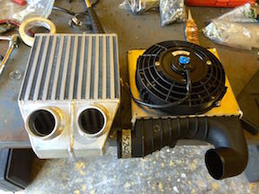
| − | + | Here is a comparison with the SAAB and a fan on it. | |
| − | + | [[File:SAAB Renault5GT compare.jpg]] | |
| − | + | [[File:SAAB Renault5GT compare-b.jpg]] | |
| − | + | You can see from the Renault is a thicker core than the SAAB | |
| − | + | [[File:SAAB Renault5GT compare-c.jpg]] | |
| − | === | + | === Oil Pump === |
| − | : | + | '''P/N:''' |
| − | + | :* 068-115-105-BP | |
| − | + | This is the DV oil-pump which is required if using the DV oil-pan | |
| − | + | === Oil Cooler === | |
| − | : | + | [http://www.thesamba.com/vw/forum/viewtopic.php?t=603839&highlight=ahu+water+pump http://www.thesamba.com/vw/forum/viewtopic.php?t=603839&highlight=ahu+water+pump] |
| − | + | '''P/Ns''' | |
| − | : | + | :* 027117021E cooler |
| − | + | :* 028115721B tube | |
| − | + | == The Process == | |
| − | + | This is where I'm going to linking to my youtube videos regarding my steps of building up a new-long block AHU engine from Bora Parts. | |
| − | + | Here is the new long-block and a used engine: | |
| − | ==== | + | : [https://www.youtube.com/watch?v=8nIr3wK__G4 Bora Parts 1z/AHU long-block & Quality German Auto used engine - video] |
| + | |||
| + | : [https://www.youtube.com/watch?v=JEq81ArLMWA Bora Parts 1z/AHU long-block - video] | ||
| + | |||
| + | === Long Block (BoraParts) build-up === | ||
| − | + | I want to state up front, that I used blue thread locker on all bolts even ones by hand. I wanted to make sure nothing rattled out. | |
| − | + | I also used lined worm gear hose clamps for all hoses. | |
| − | ==== | + | ==== Engine Cover Plate ==== |
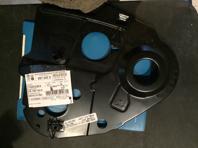
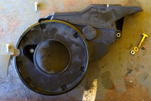
| − | + | The new-long block didn't come with an engine cover-plate. This was purchased for the engine and the corresponding mounting hardware. | |
| − | + | ===== Reference ===== | |
| − | : | + | :* [http://etka.cc/vw/part_single/catalog/vw/markt/USA/modell/PA/year/1997/drive_standart/147/hg_ug/109/subcategory/109060/part_id/3685900/lang/e ETKA] |
| − | : | + | :* Bentley 15a-11 |
===== Tools ===== | ===== Tools ===== | ||
| − | + | Blue Thread Locker | |
| − | + | Torque Wrench | |
| − | + | 10mm socket | |
| − | + | ===== P/Ns ===== | |
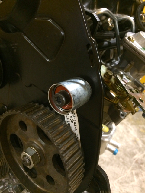
| − | + | :* 1 x 028109143H - 1Z/AHU engine cover plate | |
| − | + | :* 2 x N01021226 | |
| − | + | :* 2x N0122265 | |
| − | + | ===== Install ===== | |
| − | + | I initially started with the 028109143H cover plate and the two bolts and washers that set it into place (N01021226 & N0122265) | |
| − | + | These two 10mm bolts install at a torque pressure of 7ft/lb | |
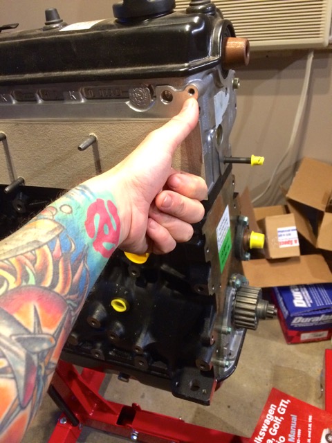
| − | + | ===== Photos ===== | |
| − | + | Cover Plate | |
| − | [[File: | + | [[File:AHU-engine-cover.jpg]] |
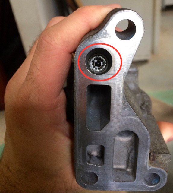
| − | + | Where my thumb points is where the bolts go to mount the engine cover to the long-block | |
| − | [ | + | [[File:AHU-engine-cover-thumb-mark.jpg]] |
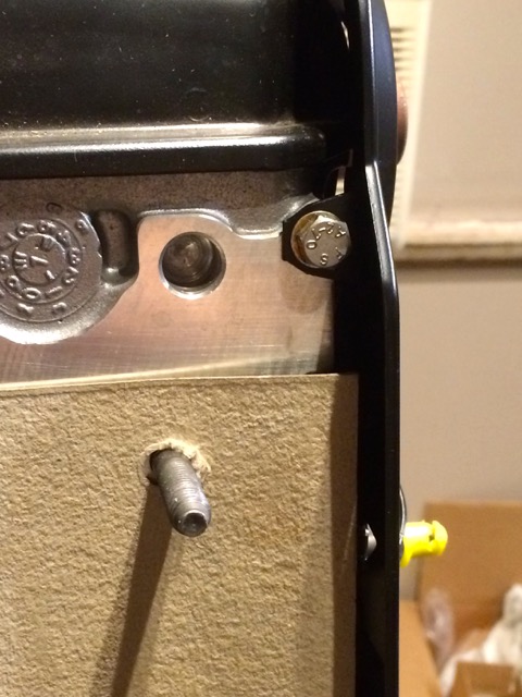
| − | + | You see how it's mounted from the side: | |
| − | + | [[File:AHU-engine-cover-mounted-bolt.jpg]] | |
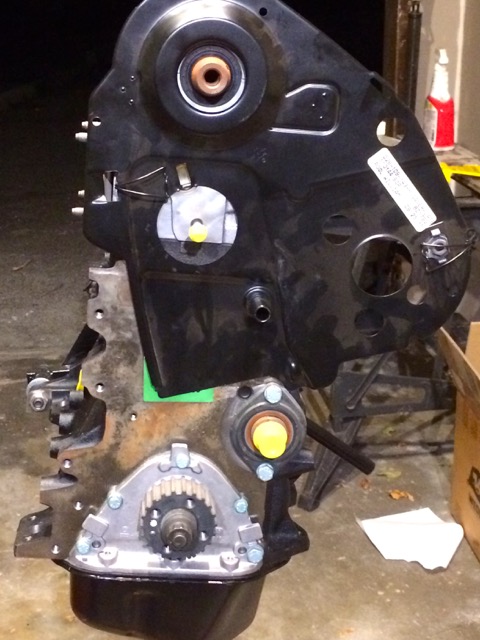
| − | + | Mounted from front | |
| − | : | + | [[File:AHU-engine-cover-mounted.jpg]] |
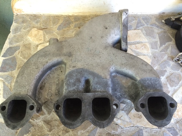
| − | ==== | + | ==== Intake ==== |
| − | : | + | '''''NOTE:''''' |
| − | + | If using an AAZ exhaust manifold which points the turbo up higher; for better drainage to the block--if you drain to the block. | |
| − | + | Get a PD130, NOT a PD150. The PD150 points towards the rear of the van. This "makes" sense till you realize it interfers with the turbo using the AAZ exhaust manifold that moves it up higher. The PD130 that points towards the front of the van is more ideal with the AAZ exhaust manifold. | |
| − | + | If you use the AHU exhaust manifold and drain into the oil sump NOT the block, then you'll likely have clearance room to use the PD150. | |
| − | + | ===== Reference ===== | |
| − | : | + | :* VW; W42-011-294-103B ''21-6'' |
| − | : | + | :* Use high-temp (2000 F) anti-seize on bolts; blue |
| − | : | + | :* Bolt hardware installed at 25Nm (18ft lb) or close to that with a torque wrench |
| − | ===== | + | ====== PD130 ====== |
| − | + | [http://www.thesamba.com/vw/forum/viewtopic.php?t=615241&postdays=0&postorder=asc&start=0 PD130/PD150 intake TheSamba article] | |
| − | + | The single large 3 bolt intake on the PD Intake Manifold that connect to your IC piping faces FRONT of the van typical on AHU install | |
| − | + | These terms are used to describe the same thing | |
| − | + | Driver side exit, right side , euro passat, longitudinal | |
| + | and is one of these part# | ||
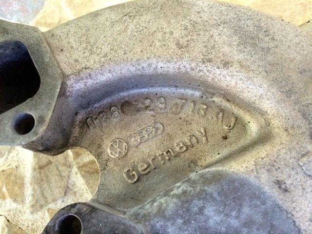
| − | + | : 038129713AJ | |
| + | : 038129713AG | ||
| − | + | The two above intakes would require an EGR delete down-pipe | |
| − | + | However, if you have an intake with the p/n 028129713N which is from a Golf 1z setup would also work a-bit more restrictive with the air. | |
| − | + | ====== PD130 Install Notes ====== | |
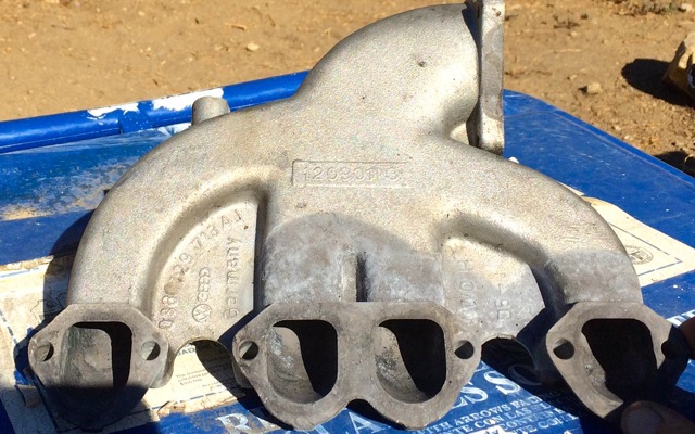
| − | + | Intake PD130 038129713AJ | |
| − | + | [[File:PD130AJ.jpg]] | |
| − | [[File: | + | [[File:PD130AJstamp.jpg]] |
| − | + | I wanted to replace the gasket and all mounting bolts | |
| − | + | [http://www.idparts.com/intake-manifold-cleaning-kit-ahu-1z-p-2417.html ID Parts Intake Manifold Cleaning Kit (AHU/1Z)] | |
| − | : | + | Which includes the parts laid out in: |
| − | + | [http://etka.cc/vw/part_single/catalog/vw/markt/USA/modell/PA/year/1997/drive_standart/147/hg_ug/129/subcategory/129045/part_id/3686577/lang/e ETKA 1997 Passat Diesel Intake Manifold] | |
| − | : | + | The kit itself includes what I need: gasket & mounting bolts |
| − | + | If obtaining a used intake (which is '''MOST''' likely the case there's various methods of cleaning it out. | |
| − | + | In my case, I used multiple (two-three days twice a day)power-washings after they sat with oven-cleaner sprayed on their intake ports. | |
| − | + | It should look like this before putting it on the long-block | |
| − | + | [[File:PD130AJ-intake-post-cleanse.jpg]] | |
| − | + | ====== PD130 hack off bosses ====== | |
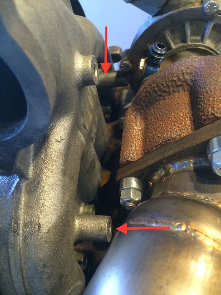
| − | + | The turbo isn't clearing the PD130 bosses and mating cleanly. | |
| − | + | Here is a youtube and photo of what I'm talking about: | |
| − | [ | + | [https://www.youtube.com/watch?v=o5531T0DNj0 Youtube Video] |
| − | + | Arrows pointing where it is not clearing | |
| − | + | [[File:K14turbo issue.jpg]] | |
| − | + | Hack off the bosses! | |
| − | ===== | + | ===== Tools ===== |
| − | :* | + | :* Torque Wrench |
| − | :* | + | :* H6 |
| − | + | ===== P/Ns ===== | |
| − | + | 1 x ''038129713AJ'' OR ''038129713AG'' | |
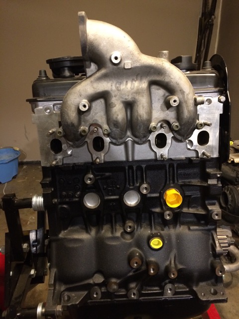
| − | ===== | + | ===== Photos ===== |
| − | : | + | [[File:AHU PD130 install.jpg]] |
| − | ===== | + | ===== Gasket Install ===== |
| − | + | The raised side goes towards the intake manifold with the indented side going towards the head | |
| − | + | ==== Exhaust ==== | |
| − | |||
| − | |||
| − | + | '''NOTE:''' Before you start see the EGT Probe section below | |
| − | + | I couldn't find the newer style as readily as the older style. I got a newer one for if I had to switch to it down the road. | |
| − | + | ===== Reference ===== | |
| − | + | :* [http://etka.cc/vw/part_single/catalog/vw/markt/USA/modell/PA/year/1997/drive_standart/147/hg_ug/253/subcategory/253030/part_id/3687217/lang/e ETKA] | |
| − | + | :* VW; W42-011-294-103B 21-2 | |
| − | + | :* Use high-temp (2000 F) anti-seize on bolts to hold the copper exhaust nuts which are to be torqued @ 25nm (18ft lb) | |
| − | + | ====== NOTES ====== | |
| − | + | If using the AAZ exhaust manifold you position the turbo higher; thus, allowing to drain to the block instead of the oil pan. | |
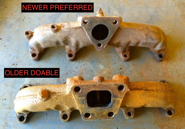
| − | + | There are TWO types of AAZ exhaust manifolds that work for this. | |
| − | + | The older trapezoid and the newer triangle, both will work; however, some notes regarding the two. | |
| − | + | OLDER - Trapezoid - Four Hole Unit - This will mount a K14 turbo stock without modification P/N 068-129-591G | |
| − | + | NEWER - Triangle - Three Hole Unit - This will mount a K03 or K03 hybrid stock turbo without modification. P/N 028-253-033R | |
| − | + | ====== AAZ Exhaust Comparison ====== | |
| − | + | Note: Newer vs Older is relative to what turbo you plan to install. | |
| − | + | [[File:AAZ Exhaust Manifold Comparison.jpg]] | |
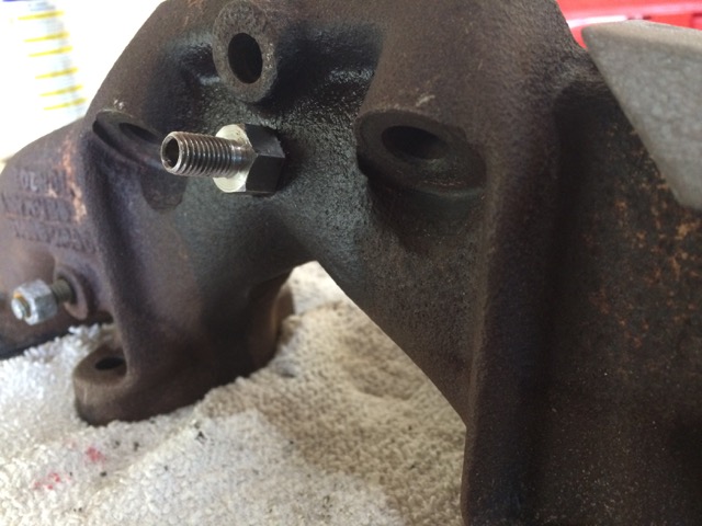
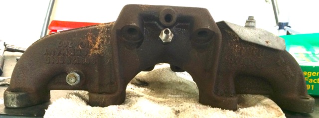
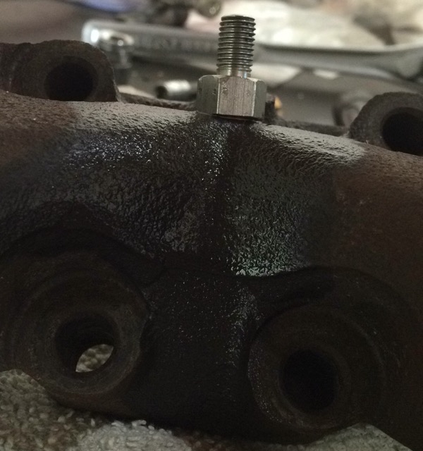
| − | + | ====== EGT Probe ====== | |
| − | + | [http://www.aircraftspruce.com/catalog/inpages/micro1pyroprobes.php Aircraft Spruce - 1/8 NTP] | |
| − | + | ===== P/Ns ===== | |
| − | + | :1 x 068-129-591G - MK1 exhaust manifold trapezoid flange | |
| − | + | :8 x N90085001- Copper plated exhaust manifold nut (8 per manifold) @ 25nm (18ft lb) | |
| − | + | :8 x N90095501 - Exhaust manifold OE washer | |
| − | + | :4 x 028-129-589B Exhaust Manifold Gasket. | |
| − | + | ===== Tools ===== | |
| − | + | :* 12mm socket | |
| − | + | :* Torque wrench | |
| − | + | :* Permatex Ultra Copper | |
| − | + | :* Blue LocTite | |
| − | + | ===== Gasket Install ===== | |
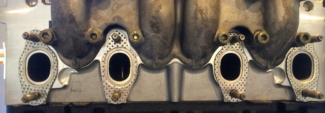
| − | + | Per Libby: "The metal ring on the exhaust manifold gaskets can face either the head or the manifold and in fact, two *should* face the head and two should face the manifold. There is a horizontal line of symmetry through the exhaust manifold, but if you place a vertical line through the fastener holes, the ports are offset 4-5mm toward the center of the engine. In other words, the two ports on the pulley end of the head are offset toward the flywheel and the two at the flywheel end of the head are offset toward the pulleys. The exhaust gaskets need to be oriented so that the offset is the correct direction. Furthermore, if you look where the gasket surrounds the stud, there is a skinny side and there is a side that has more material. The skinny side should be oriented closer to the intake manifold." | |
| − | + | Then a light smear of permatex copper on both sides of the exhaust manifold gaskets | |
| − | + | Here is how the gaskets should look orientated before the permatex sealer | |
| − | + | [[File:AHU exhaust gasket orientation.jpg]] | |
| − | + | ===== Video ===== | |
| − | = | + | : [https://www.youtube.com/watch?v=UeSpzUj3lVw Exhaust Manifold Installation Video] |
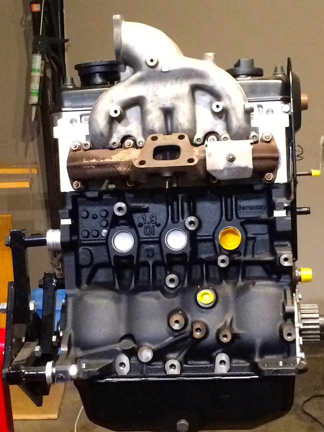
| − | ===== | + | ===== Photo ===== |
| − | + | [[File:AHU exhaust manifold.jpg]] | |
| − | ===== | + | ===== EGT Probe ===== |
| − | + | ====== Reference ====== | |
| − | + | :* [http://www.vanagondiesel.info/index.php/MTDI_AHU_Conversion_Notes#EGT_Probe_2 Wiki] | |
| − | + | ====== Photos ====== | |
| − | + | UPDATE; The below tap location works, but so does tapping the above stud when imused on an AHU. I wasn't aware then. Verified by Karl M. | |
| − | + | [[File:AAZ exhaust-EGT-a.jpg]] | |
| − | + | [[File:AAZ exhaust-EGT-b.jpg]] | |
| − | + | [[File:AAZ exhaust-EGT-c.jpg]] | |
| − | ==== | + | ==== Vacuum Pump ==== |
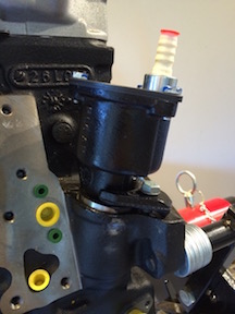
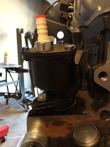
| − | This is a | + | I had made a video, but I lost it. This is a very simple process, so I will just explain it here. |
| − | + | If you look at the end of the vacuum pump you'll see it has a slot. Then when you look into the engine hole a receiver for that slot. The goal is to lube it up a little with diesel oil so it's not totally dry. Then go in the angle of the slot. I usually turn clock-wise till it falls seated. One way of knowing if it's seated or not is you won't be able to see the greenish/gray O-ring as shown in the photos below. Then just tighten up the bolt and bracket. In order to get the bolt to even up enough to screw into the hole for the bracket, you may have to wiggle the bracket a little. | |
| − | ==== | + | ===== Reference ===== |
| − | + | [http://etka.cc/vw/part_single/catalog/vw/markt/USA/modell/PA/year/1997/drive_standart/147/hg_ug/145/subcategory/145000/part_id/3686916/lang/e ETKA - Vacuum Pump] | |
| − | + | VW Repair: W42-011-294-103B p13-10 | |
| − | + | ===== Tools ===== | |
| − | + | :* 13mm open-wrench | |
| − | + | ===== P/Ns ===== | |
| − | + | : 1x 028145101A - AHU vacuum pump | |
| − | : | + | : 1x N0102336 - hexagon bolt; M8X28 (13mm @ 20nm) |
| − | : | + | : 1x N01224110 - spring washer; B8X15 |
| − | : | + | : 1x 028905256 - bracket |
| − | + | : 1x 068145117B - Vacuum Pump Bottom Sealing Washer | |
===== Photos ===== | ===== Photos ===== | ||
| − | + | Final photos of installation | |
| − | [[File: | + | [[File:Vpump-installed1.jpg]] |
| − | + | [[File:Vpump-installed2.jpg]] | |
| − | + | ==== CrankCase Breather Valve Assembly ==== | |
| − | + | ===== Reference ===== | |
| − | + | [http://etka.cc/vw/part_single/catalog/vw/markt/USA/modell/PA/year/1997/drive_standart/147/hg_ug/103/subcategory/103080/part_id/3687726/lang/e ETKA - Ventilation for Cylinder Head Cover Diagram] | |
| − | ===== | + | ===== P/Ns ===== |
| − | : | + | : 1 x 028129101D - PCV/CCV Valve (A3) (B4) |
| + | |||
| + | : 1 x 028103491J - CCV Breather Tube (A3 B4 AHU 1Z) | ||
| − | : | + | : 1 x N 90466301 - o ring for breather tube |
| − | + | : 1 x 028103500 - CCV Valve Rubber Boot | |
===== Tools ===== | ===== Tools ===== | ||
| − | :* Blue | + | :* Blue coded thread-locker was used on tube mount bolts. |
| − | :* | + | :* H6 @ 7ft lbs |
| − | + | ===== Photo ===== | |
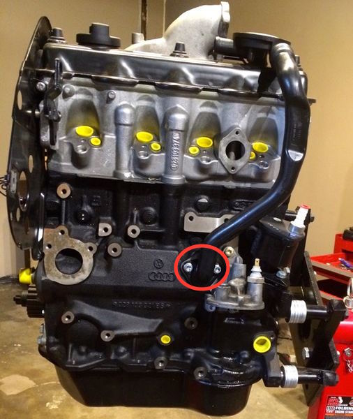
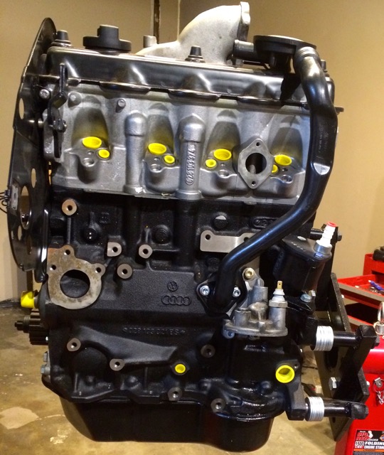
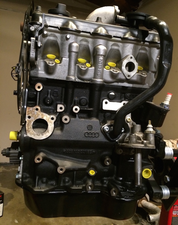
| − | + | The red oval is the only bolts you have to tighten and the puck at the top goes into the breather hole | |
| − | : | + | [[File:AHU-CCV-tube.jpg]] |
| − | + | ==== Oil Filter Flange ==== | |
| − | + | ===== NOTES ===== | |
| − | : 1 | + | : 053115417A - Oil filter flange; This flange has been used for all the 1.8-1.9 gas and diesel engines (AAZ, 1Z and early AHU). The difference being the later AHU adaption have two 10mm ports and one 12mm port (for the Banjo Bolt N0210717) instead of the three 10mm ports that the gas/ABA engines use. There's no 'real' way to know which you get by searching for the P/N. Your best luck appears to be searching for a "MK3 TDI oil filter flange" or maybe "AHU" also in the search string. |
| − | + | There's also two other indicators of the proper one you received. | |
| − | + | First the third port is larger than the first two. (photo coming soon of comparison) | |
| − | + | The second visual indicator is a bit more positive you got the right one from what I have read on the forums and Parts Base. | |
| − | + | Within the below photo in the red circle is ''028115436 - choke; M12X1,5; AAZ,,AHU,1Z'' which is what you want for the diesel engines. From my research, and what I received the first time, gasser engines do not contain this. | |
| − | [[File: | + | [[File:VWPN053115417Aw028115436.jpg]] |
| − | ===== | + | ===== Reference ===== |
| − | + | [http://etka.cc/vw/part_single/catalog/vw/markt/USA/modell/PA/year/1997/drive_standart/147/hg_ug/115/subcategory/115050/part_id/3686021/lang/e ETKA] | |
| − | + | VW Repair: W42-011-294-103B p13-10 | |
| − | ===== | + | ===== Tools ===== |
| − | + | :* Blue Thread Locker | |
| − | + | :* H6 | |
| − | + | ===== P/Ns ===== | |
| − | + | : 1x 028115436 - choke; M12X1,5; AAZ,,AHU,1Z | |
| − | + | : 1x N0160243 or N0160241 - sealing plug; M10X1; ADD,AHU,1Z | |
| − | + | : 1x N0138115 - o-ring; 10X13,5; ADD,AHU,1Z | |
| − | + | : 2x N0903151 - socket head bolt with hexagon; socket head (combination); M8X25 | |
| − | + | : 1x N90425401 - socket head bolt with hexagon; socket head (combination); M8X40; ADC,ADD,ACC,; AHU,1Z @ 25Nm | |
| − | + | : 1x 028115441C - oil filter seal | |
| − | + | :: 1x 068919081A - Oil Pressure Switch [OEM] (A3)(B4) - This is NOT needed in the Diesel Vanagon setup, it's here as a reference do NOT get it. | |
| − | + | : 1x N0210717 - Oil Filter Oil Feed Line Banjo Bolt - You MAY get this included when you get an oil-return line, so you may want to hold off on this. | |
| − | + | ===== Photos ===== | |
| − | + | Here is the oil filter Flange installed: | |
| − | [[File: | + | [[File:Oil-filter-installed.jpg]] |
| − | === | + | ===== Video ===== |
| − | = | + | : [https://www.youtube.com/watch?v=oycvdTQM2ss Youtube - Installing Oil Filter Flange] |
| − | + | ==== Oil Filter Union ==== | |
| − | + | This is maybe the easiest part to install. You just screw it in. I put some blue thread locker on it. It doesn't matter which end screws into the oil-filter. | |
| − | ===== | + | ===== P/Ns ===== |
| − | + | 1x 028115721B - union tube | |
| − | + | ===== Photo ===== | |
| − | + | End result: | |
| − | [ | + | [[File:Oil-filter-installedwunion.jpg]] |
| − | + | ==== Aux Oil Cooler ==== | |
| − | + | ===== Reference ===== | |
| − | + | :* [http://etka.cc/vw/part_single/catalog/vw/markt/USA/modell/PA/year/1997/drive_standart/147/hg_ug/115/subcategory/115050/part_id/3686021/lang/e ETKA] | |
| − | : | + | :* [http://forums.tdiclub.com/showthread.php?t=78993 Oil Cooler Options] |
| − | + | ===== P/Ns ===== | |
| − | : | + | Choose an Oil Cooler: |
| − | : | + | : 1x 028117021E - oil cooler V6 4Motion Cooler - Good for Stock AHU engines |
| + | ::* 1x 028117070B - oem cooler seal. The febi one sucked | ||
| − | : 2 | + | : 1x 038117021B - oil cooler for a 2.0 TDI engine - Good for Enhanced AHU Engines |
| + | ::* 1x 038117070B - oem cooler seal. | ||
| − | + | Get the tube & nut; same for both O/Cs | |
| − | : | + | : 1x 028115721B - union tube |
| − | : | + | : 1x 068115723 - hexagon nut; ADC,AAZ,ABA,; AHU,1Z |
| − | + | ===== Installation ===== | |
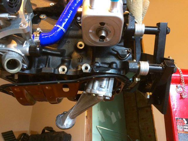
| − | + | This is pretty simple just slide it over the (028115721B - union tube) into the oil-filter assembly. The ports will face left of the engine indicated in the photo below. If you look at the top of the cooler and inside the flange you'll see the 'oil' feed line hole. Those basically need to match up. | |
| − | + | Then place the oil-cooler over it and attach with the (068115723 - hexagon nut) | |
| − | + | ===== Photo ===== | |
| − | : | + | End result: |
| − | : | + | [[File:AHU-oil-cooler-install.jpg]] |
| − | : | + | This is what a 2.0 TDI O/C with Karl's moddification done installed looks like: |
| − | : | + | [[File:PD130TDI OC.jpg]] |
| − | ==== | + | ==== Oil Pan ==== |
| − | + | This section will include details on swapping the 1.6na DV oil-pan for a 50 degree install, as also the 4cyl windage tray for it. At the same time we'll be swapping in an 82' diesel oil-pump to get the desired plunge shaft length. | |
| − | : | + | '''''NOTE:''''' You must leave the oil-pan loose and mate to the transmission first THEN once the transmission is mounted tighten up the oil-pan along the edge level to the block. In addition, there are TWO bolts near the flywheel that are hard to reach. You'll need to rotate the flywheel and use the elongated space to tighten those two bolts. Make sure to dab a little bit of loctite on those two bolts. You do NOT want them coming loose by accident. |
| − | ==== | + | ===== Reference ===== |
| − | + | :* [http://etka.cc/vw/part_single/catalog/vw/markt/USA/modell/VA/year/1982/drive_standart/4/hg_ug/103/subcategory/5010/part_id/3685688/lang/e ETKA - 82' Vanagon CS 1.6na Cylinder Block with Oil Sump] | |
| − | + | :* [http://etka.cc/vw/part_single/catalog/vw/markt/USA/modell/VA/year/1982/drive_standart/4/hg_ug/115/subcategory/10010/part_id/3685993/lang/e ETKA - 82' Oil Pump] | |
| − | + | :* [http://etka.cc/vw/part_single/catalog/vw/markt/USA/modell/PA/year/1997/drive_standart/147/hg_ug/103/subcategory/103020/part_id/3685688/lang/e ETKA - 97' Passat AAZ 1.9TD Cylinder Block with Oil Sump & Windage Tray] | |
| − | : | + | :* VW; W42-011-294-103B 13-12 |
| − | + | ===== Tools ===== | |
| − | + | :* 13mm socket 6point | |
| − | + | ===== DV Pan swap to AHU ===== | |
| − | + | Its as recommended to get longer oil-pan screws for the windage tray, but the stock 1.6na CS engine DV pan comes with the following 20 bolt size M6x22 | |
| − | + | Get M6X25 for clearing the windage tray @ 10Nm or 7ft/lbs. VW specs a good bolt for this p/n N10302402 | |
| − | + | These should be tightened to 7ft/lbs | |
| − | + | Now for the actual windage tray itself. It was included with the AAZ and sometimes with the 1Z and AHU engines, but was more common in the gasser inline 4's. It was NOT part of the 1.6na engine. | |
| − | + | That said, my 1Z came with a windage tray, but sometimes the sealant is so bad it fucks the seal up and you'll need to get a new one. | |
| − | : | + | The Windage Tray P/N is: 037115220B |
| − | + | ===== DV Oil Pump Swap ===== | |
| − | + | You need to use the DV oil-pump NOT the AHU oil-pump; unless you modify it by moving the DV pickup to the AHU oil pump. | |
| − | + | ====== Reference ====== | |
| − | :* | + | :* Bentley 17-1 - 1Z / AHU specific |
| − | + | :* VW W42-011-294-103B p17-6 | |
| − | + | Once you have the oil-pan off the AHU you'll see the oil-pump. However, if you're long-block is like mine it ''may'' have a windage tray installed. | |
| − | + | ====== P/Ns ====== | |
| − | : | + | :* 068-115-105BP |
| − | + | ====== Photos ====== | |
| − | + | AHU Windage Tray Installed | |
| − | [[File:AHU- | + | [[File:AHU-windage-tray.jpg]] |
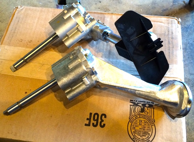
| − | + | Now you'll see the oil-pump as the silver device with the black tray delay off to the left. This is the oil pump you need to swap. | |
| − | + | Here is the AHU (black pickup) oil-pump vs a new DV oil-pump (all metal) | |
| − | + | [[File:AHU CS oil-pump-comparison.jpg]] | |
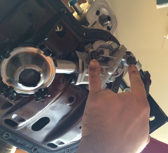
| − | + | You'll see two bolts (black heads for me) where my fingers point. These will remove the oil-pump (13mm) | |
| − | : | + | [[File:AHU oil pump removal.jpg]] |
| − | + | When installing the DV oil-pump the two pump bolts get torqued at 20Nm | |
| − | : | + | '''''NOTE:''''' The AHU oil-pump bolts are LONGER than the DV oil-pump bolts. If you do not have the original DV Oil Pump bolts you need to get two of either of the following P/Ns: N01037510 or N0103753 with the spring-washers N0122265 |
| − | + | ====== Installing Oil Pump & Windage Tray ====== | |
| − | + | See the note above about final tightening that happens AFTER the transmission has been mated to the engine! When ready to tighten, use blue thread locker for the bolts. It helps keep everything snug. | |
| − | + | I've seen two types of AHU windage trays. OEM and from Victor Reinz. The VR ones are slightly larger where they can with caution and care fit over the DV oil-pump. The OE ones do not. | |
| − | + | I just suggest installing the pump first (the bolts will be 13mm tigten to 20Nm) and with blue thread tocker. At that point you can let the windage tray hold on the pump like this | |
| − | : | + | [[File:DV OIL PUMP AHU INSTALL.jpg]] |
| − | |||
| − | |||
| − | + | Then put on the oil-pan with the bolts hand-tighten / semi loose, as to protect the pump. You should have something like this | |
| − | ''' | + | NOTE: The down-pipe isn't in the proper orientation. I didn't know better at the time of this photo. It's an unessary detail unless it caught your eye to; wtf? |
| − | + | [[File:MTDI AHU loosebolted-DV pan.jpg]] | |
| − | + | ==== Tooth Belt Guard Tensioner Roller ==== | |
| − | + | ===== Reference ===== | |
| − | [ | + | :* [http://etka.cc/vw/part_single/catalog/vw/markt/USA/modell/PA/year/1997/drive_standart/147/hg_ug/109/subcategory/109060/part_id/3685900/lang/e ETKA] |
| − | + | ===== P/N ===== | |
| − | + | : 1 x 028109243F | |
| − | ==== | + | ===== Tools ===== |
| − | + | :* 13mm socket @ 25Nm | |
| − | + | ===== Installation ===== | |
| − | + | Very simple just slide it over, lock the latch into the engine cover plate. Then tighten the nut @ 25Nm | |
| − | + | ===== Video ===== | |
| − | : | + | : [https://www.youtube.com/watch?v=F4_Wp6q4BlI&feature=youtu.be Youtube] |
| − | ===== | + | ===== Photo ===== |
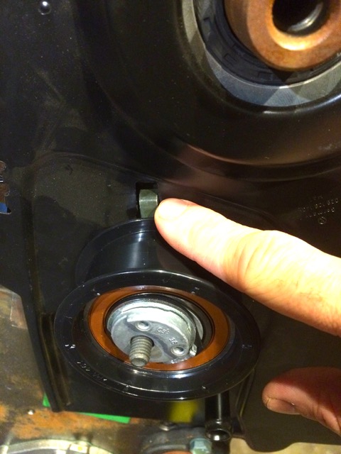
| − | + | This is a photo of where the locking slot of the tensioner goes | |
| − | + | [[File:AHU-tension-idler.jpg]] | |
| − | + | ==== ABF Serpentine Setup ==== | |
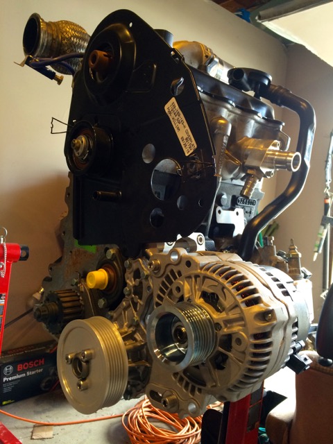
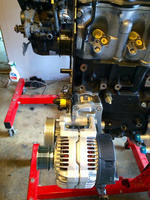
| − | + | This bracket and setup, WILL keep your alternator lower than the deck-lid; thus, the arm on the IP being the only possible interference. That interference though is negligent, as you just trim the foam for clearance of the throttle arm. However, if you need to cut-out the deckled here's a [[File:Andrew Libby Engine Lid Template.pdf]] template for you. | |
| − | |||
| − | + | Since I don't have power-steering nor do I have air-conditioning, I can simplify my setup and make it more reliable with a serpentine setup rather than a v-belt system. | |
| − | + | This can be accomplished via various methods as mentioned below. I went the ABF way | |
| − | + | ===== Reference ===== | |
| − | + | I ended up using a system from [http://www.iabedindustries.com/ iABED Industries] found on the [http://forums.vwvortex.com/showthread.php?3490384 VWVortex] | |
| − | + | He makes a custom bracket, that's really beautiful, but if you want to source / find your own VW specific parts read these threads: | |
| − | + | :* [http://forums.vwvortex.com/showthread.php?3335420 VWVortex - The definitive deleting your A/C in multiple ways thread] | |
| − | + | :* [http://forums.vwvortex.com/showthread.php?3379568-ABF-alternator-bracket-Part-number VWVortex ABF alternator bracket Part number ???]] | |
| − | + | :* [http://forums.vwvortex.com/showthread.php?3095335 VWVortex - Thread: Let me show you my....serpentine (reference) ] | |
| − | + | The Alternator I ended up using was an ABF Bosch reman 90a - AL0187X (VW # 028 903 025 P) | |
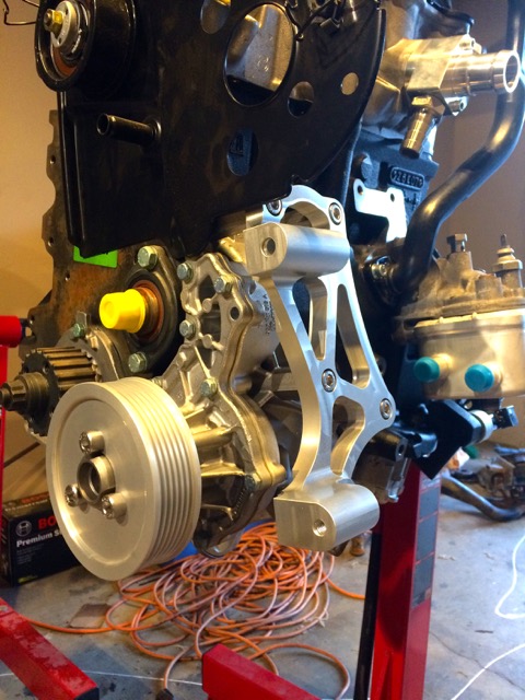
| − | + | ===== Photos ===== | |
| − | + | iABED Industries ABF Bracket | |
| − | + | [[File:MTDI-AHU-ABFserp-bracket.jpg]] | |
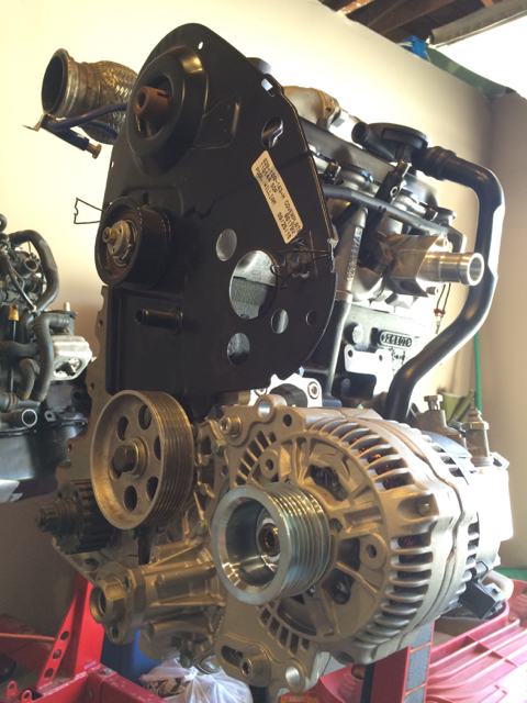
| − | + | Alternator installed with the bracket and pulley's installed. | |
| − | + | [[File:MTDI-AHU-ABFserp-installed-a.jpg]] | |
| − | + | [[File:MTDI-AHU-ABFserp-installed-b.jpg]] | |
| − | + | ==== Intermediate Shaft Pulley ==== | |
| − | ===== | + | ===== Reference ===== |
| − | :* | + | :* [http://etka.cc/vw/part_single/catalog/vw/markt/USA/modell/PA/year/1997/drive_standart/147/hg_ug/115/subcategory/115020/part_id/3685993/lang/e ETKA - Oil Pump & Crank Shaft] |
| − | :* | + | :* [http://www.myturbodiesel.com/wiki/intermediate-shaft-seal-replacement-mk3-vw-jetta-passat-tdi-1z-ahu/ MyTurboDiesel - Intermediate Shaft Seal Replacement Guide] - If you want to replace yours. Mine on the long-block looked new. |
| − | + | VW; W42-011-294-103B 13-4 | |
| − | + | ===== Tools ===== | |
| − | + | :* Blue Thread Locker | |
| − | : | + | :* 22mm socket |
| − | : | + | :* Sprocket Countersink Tool |
| − | + | ===== P/Ns ===== | |
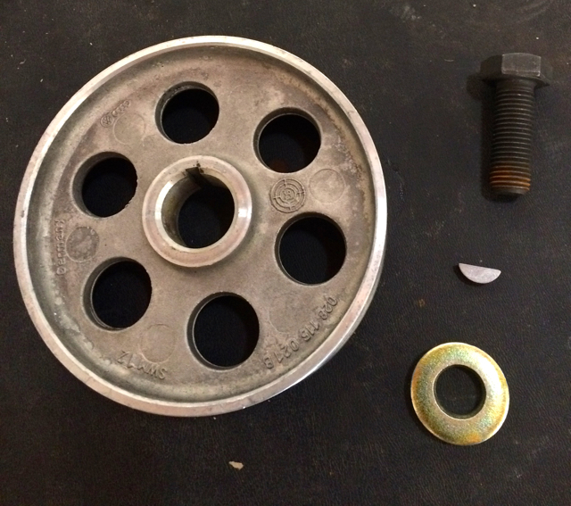
| − | : | + | : 1 x VW# N012708 - 2sprocket woodruff key |
| − | : | + | : 1 x VW# 028-119-021B - intermediate shaft (in case yours is broken, don't have one off a used engine, etc.) The part numbers / VW logos go towards the engine (i.e. where you can't see them) |
| − | + | : 1 x VW# N0101371 - Hexagon Bolt M12X1,50X35 @ 45 Nm / 33 ftlb | |
| − | + | : 1 x VW# 027109143 - washer | |
| − | + | : 1 x intermediate shaft /camshaft seal (47x32x10mm) "026 103 085 d" or "068 103 085 e" | |
| − | ==== | + | ===== Photos ===== |
| − | + | ====== Sprocket Tool ====== | |
| − | + | This is the tool / setup you want to remove/install. This was on my used engine, but same applies for this build-up. | |
| − | + | [[File:VW SPROCKET REMOVAL TOOL.jpg]] | |
| − | ===== | + | ====== Intermediate Shaft Parts ====== |
| − | + | You should have these parts | |
| − | + | [[File:AHU intermediate shaft pulley.jpg]] | |
| − | + | ====== Intermediate Shaft Woodruff Key Install ====== | |
| − | : | + | Position it like this: |
| − | + | [[File:AHU intermediate shaft pulley-woodruff-install.jpg]] | |
| − | + | Then set it into the groove like this: | |
| − | : | + | [[File:AHU intermediate shaft pulley-woodruff-install-b.jpg]] |
| − | + | ====== Intermediate Shaft Mounted ====== | |
| − | + | It should slide on like so: | |
| − | : | + | [[File:AHU intermediate shaft pulley-mounted.jpg]] |
| − | + | ====== Sprocket Countersink Tool Mount Points ====== | |
| − | + | Place the sprocket tool at these locations when you tighten the center bolt | |
| − | + | [[File:AHU intermediate shaft pulley-sprocket-tool-points.jpg]] | |
| − | + | ====== Intermediate Shaft Pulley Installed ====== | |
| − | + | It should look like this when done | |
| − | + | [[File:AHU intermediate shaft pulley-installed-b.jpg]] | |
| − | + | [[File:AHU intermediate shaft pulley-installed.jpg]] | |
| − | + | === Coolant Pump === | |
| − | + | ==== Reference ==== | |
| − | :* | + | :* [http://etka.cc/vw/part_single/catalog/vw/markt/USA/modell/PA/year/1997/drive_standart/147/hg_ug/121/subcategory/121010/part_id/3686048/lang/e ETKA - Coolant Pump] |
| − | :* | + | :* VW; W42-011-294-103B 19-6 |
| − | + | ===== Serpentine or non ===== | |
| − | == | + | [http://www.thesamba.com/vw/forum/viewtopic.php?p=7673431#7673431 http://www.thesamba.com/vw/forum/viewtopic.php?p=7673431#7673431] |
| − | + | If you don't have A/C or PS, you can use the VR6 water pump pulley (028-121-031-E) and use the serp belt to run the Alt and water pump. | |
| − | : | + | Decided to get a serpentine setup done via INA Engineering: |
| − | : | + | [http://forums.vwvortex.com/showthread.php?3871186 http://forums.vwvortex.com/showthread.php?3871186] |
| − | : | + | [http://forums.vwvortex.com/showthread.php?3379568-ABF-alternator-bracket-Part-number http://forums.vwvortex.com/showthread.php?3379568-ABF-alternator-bracket-Part-number] |
| − | + | [http://forums.vwvortex.com/showthread.php?3335420 http://forums.vwvortex.com/showthread.php?3335420] | |
| − | + | ==== P/Ns ==== | |
| − | + | : 1 x 037-121-013A - Coolant Pump Assembly | |
| − | + | : 1 x 056-121-121B - Alloy thermostat housing | |
| − | + | : 1 x 4256.87D50 - 87 degrees thermostat | |
| − | + | : 1 x 038-121-119B - o-ring | |
| − | + | : 2 x N902-809-04 @ 10Nm | |
| − | + | : 1 x 1H0121687A - o-ring; 28,5X3,8 | |
| − | + | : 1 x 038-121-119B - o-ring; 50X4 | |
| − | + | : 1 x 028-260-821 - stud with shoulder | |
| − | + | : 2 x 028-260-821A - stud with shoulder | |
| − | + | : 1 x 028-260-821D - hexagon bolt; M8X34 | |
| − | + | : 1 x 028-260-821C - stud with shoulder; M8X17X24 | |
| − | + | : 2 x N 902-80-904 - hexagon head bolt (combi); M6X22 | |
| − | + | : 3 x N903-08-607 - socket head bolt with; inner multipoint head; M8X14 | |
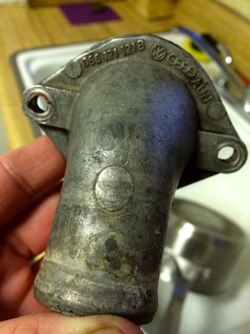
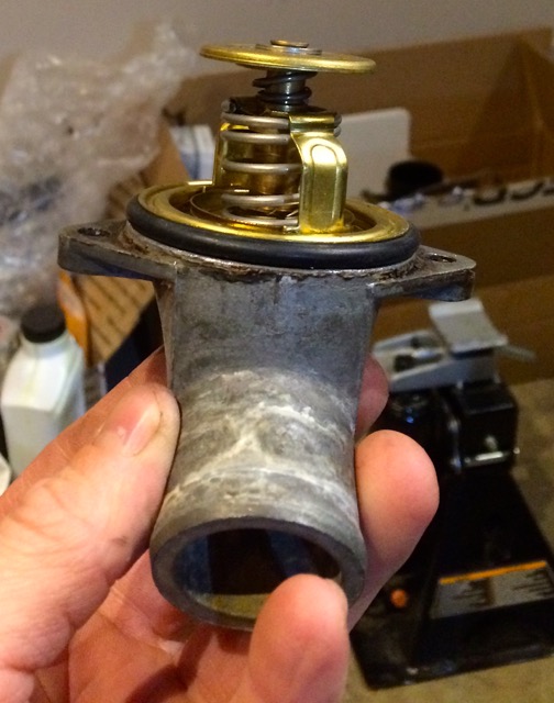
| − | + | : 1 x 056-121-121B - this is NOT the normal AHU thermostat housing flange. Instead it's the one used for the 1.6na engine. However, it is a metal alloy and more durable than the newer plastic ones. It also has the proper hose fitting for the vanagon diesel hoses. | |
| − | |||
| − | |||
| − | + | : 6PK1045 Serpentine Belt; Alternator | |
| − | + | : 028-121-031-E - VR6 Water Pump Pulley P/N if you use this setup over the serpentine setup | |
| − | ==== | + | ====Tools ==== |
| − | + | :* Blue thread Locker on bolts | |
| − | :* | + | :* 19mm wrench |
| − | + | ==== Installation Notes ==== | |
| − | : | + | '''NOTE:''' don't put the pulley on till you are ready to put the lower belt cover on. Otherwise you'll ust be taking it off again down the road; learn from me! |
| − | + | Make sure your coolant pump came or you purchased the o-rint that goes between it and the long-block. | |
| − | + | There are three shoulder bolts that look the same; | |
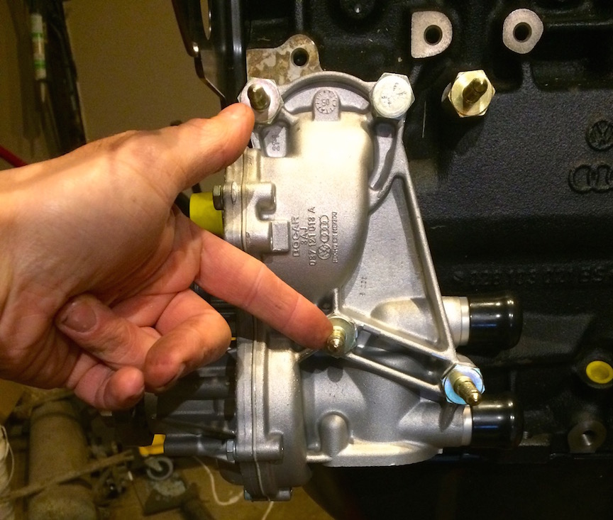
| − | + | : 1 x 028-260-821 | |
| − | : | + | : 2 x 028-260-821A |
| − | + | The one my thumb is pointing to is 028-260-821 which is shorter than the two 028-260-821A that my index finger points to | |
| − | + | The other two which are not clear in the reference points go as the following: | |
| − | + | : 1 x 028-260-821D - hexagon bolt; M8X34 - This is the first one to the right of 028-260-821. | |
| − | + | : 1 x 028-260-821C - stud with shoulder; M8X17X24 - this is to the right of 028-260-821D | |
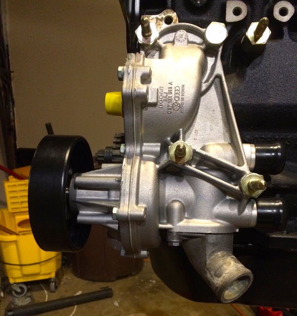
| − | + | [[File:AHU coolant pump mounted.jpg]] | |
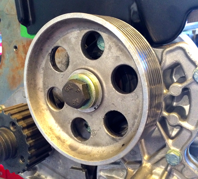
| − | + | ===== Water Pump Pulley - OLD Non Serp Setup ===== | |
| − | + | This is what I intended to use, but later changed to something else. A simpler ABF serpentine setup which I'll reference when I start that. | |
| − | + | :* Tighten bolts to 25Nm | |
| − | + | '''Tools''' | |
| − | + | :* Torque Wrench | |
| − | + | :* H6 | |
| − | + | :* Screw Driver | |
| − | + | ====== Installation Notes ====== | |
| − | + | There's a round hole on the pulley that you can put a screw driver into to lock it so it doesn't turn while you tighten the bolts. | |
| − | + | '''''Proper Tool Warning!!!''''' I found out after doing this from a peer-reviewer the tool you want is the water pump pulley tool. You can find it under one of these reference P/Ns: | |
| − | : | + | : 96280, SCH96280, UN1203280 |
| − | + | In the photo below you can see it going right from the top bolt. | |
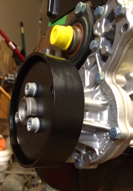
| − | + | Also, note the deeper part of the pulley goes towards the engine or the VW P/N faces away from the engine. | |
| − | : | + | [[File:AHU-coolant-pump-pulley.jpg]] |
| − | + | ===== Thermostat & Housting ===== | |
| − | + | '''Reference''' | |
| − | : | + | :* [http://www.vanagondiesel.info/index.php/MTDI_AHU_Conversion_Notes#Coolant_Pump_2 wiki] |
| − | : | + | :* [http://etka.cc/vw/part_single/catalog/vw/markt/USA/modell/PA/year/1997/drive_standart/147/hg_ug/121/subcategory/121010/part_id/3686048/lang/e ETKA - Coolant Pump] |
| − | : | + | :* VW; W42-011-294-103B 19-9 |
| − | + | '''Tools''' | |
| − | : | + | :* 10mm socket |
| − | : | + | :* Blue thread Locker on bolts |
| − | : | + | ====== Installation Notes: ====== |
| − | + | When screwing the housing to the water-pump, it may not look like it will seat in; however, the more you tighten the bolts the more it will slide up with the O-ring. | |
| − | + | ====== P/Ns ====== | |
| − | : | + | : 1 x 4256.87D50 - 87 degrees thermostat |
| + | |||
| + | : 1 x 038-121-119B - o-ring | ||
| − | : | + | : 2 x N902-809-04 @ 10Nm |
| − | + | '''Photos''' | |
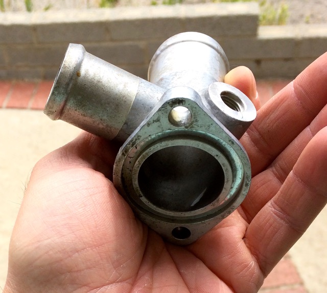
| − | : | + | The thermostat housing used from a 1.6na engine. It's an alloy one: |
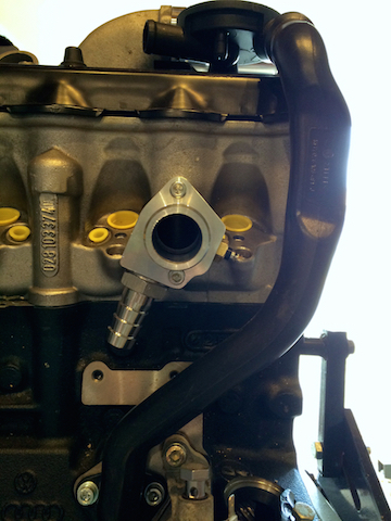
| − | + | [[File:1.6na thermostat housing.jpg]] | |
| − | + | This is how the mounting orientation should go against the coolant pump | |
| − | [[File: | + | [[File:Thermostat-housting-mount-direction.jpg]] |
| − | + | How it all looks installed | |
| − | + | [[File:Thermostathoustinginstalled.jpg]] | |
| − | + | ==== Coolant Flanges ==== | |
| − | + | '''References:''' | |
| − | + | :* ETKA - [http://etka.cc/vw/part_single/catalog/vw/markt/USA/modell/VA/year/1982/drive_standart/4/hg_ug/121/subcategory/16020/part_id/3685695/lang/e 1982 Vanagon, coolant hoses and pipes DIESEL:CS] - This helps show where on the CS it's flange would go | |
| − | [ | + | :* ETKA - [http://etka.cc/vw/part_single/catalog/vw/markt/RDW/modell/IMD/year/1982/drive_standart/422/hg_ug/121/subcategory/121020/part_id/0/lang/e 82' CS cylinder head coolant flange] |
| − | + | :* ETKA - [http://etka.cc/vw/part_single/catalog/vw/markt/USA/modell/PA/year/1997/drive_standart/147/hg_ug/121/subcategory/121070/part_id/3686128/lang/e 1997 Passat cooler for coolant reservoir flange] - This helps show where on the AHU it's flange would go | |
| − | [ | + | :* Samba - [http://www.thesamba.com/vw/forum/viewtopic.php?p=8073948#8073948 AAZ Coolant Sensor] |
| − | + | ===== Block to Pump Flange ===== | |
| − | + | I thought long and hard how to approach the mTDI coolant flange dilemma. | |
| − | + | There's a few various options to accomplish this: | |
| − | + | * Use the 1.6na aluminum flange p/n 068-121-133M with an adaptor plate to position the adaptor similar to the AHU orientation. The photos I saw of this looked like it'd cause a possible other leak, looked hooky, and just bad in my eye. | |
| − | + | * Use the later AAZ sensor p/n 357-919-501 | |
| + | green ring) on the plastic AHU flange p/n 028-121-132A This solution is bad for two reasons to me. First it's plastic and in my mind more prone to cracks. Second now you've mix-matched the sensors on the engine. | ||
| − | + | * Custom baby! | |
| − | + | In the end I felt a custom solution was the cleanest and best solution. For the following reasons: | |
| − | The | + | 1.) The material will last the lifetime of the van similar to how the 1.6na flange would; however, using the 1.6na flange you have to modify the hose route which isn't too clean to me; more parts. Or you would have to create a modification plate which in the photos I saw looked kinda hooky more possible leaks. |
| − | + | 2.) I could have went with the normal flange itself and blocked the over-flow barb (which over time may need replacement) and used a later AAZ temp sensor (for coolant temp & glow plug), but then you have a mix-match set of sensors on the van. This would make over-all support a bit more "specialized". The custom flange mimics the diesel setup to the T. | |
| − | + | I already have a sensor at the front of the engine block for the glow-plug, so that'd just be 'blocked up' using an AHU flange which is dumb. The engineer in me says mixing sensors makes supporting more a chore. | |
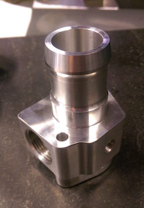
| − | + | Custom mTDI AHU diesel vanagon coolant flange from [https://www.facebook.com/LegacyMoldandTool/ Legacy Mold & Tool] talk to Charlie! (502) 348-8151 | |
| − | + | '''''NOTE:''''' The correct hose barb I have installed is a 3/4" NPT to 1" ID (the one pictured be low is a 3/4" ID which I found out was wrong) | |
| − | + | '''''NOTE:''''' The bolts on the flange are M6x55 and torque at 7nM, just use blue threadlocker and tighten snug by hand | |
| − | + | ====== Photos ====== | |
| − | [ | + | [[File:Modded-AHU-mTDI-flange.jpg]] |
| − | [ | + | [[File:MTDI-modded-AHU-coolang-flange.jpg]] |
| − | + | Comparison to the CS one (068-121-133M): | |
| − | + | [[File:CS-coolant-flange-068121133M.jpg]] | |
| − | + | ===== End of Head Flange ===== | |
| − | + | Also, I am trying to swap the AHU flange 028121145 (Flange With Glow Plug Mounting) with a 1.6na 068121145K one. | |
| − | + | There are two 1.6na flanges one with two sensor ports another with one. If you get the two version and want the plug a hole get the following o-ring and plug: | |
| − | + | ====== Tools ====== | |
| − | + | :* Blue thread locker | |
| − | : | + | :* 14mm wrench |
| − | : | + | :* 10mm wrench |
| − | : | + | :* H5 |
| − | + | ====== Mounting Bits ====== | |
| − | + | :1 x Plug: N0160243 or N0160241 | |
| + | |||
| + | :1 x O-ring: N 0138115 | ||
| − | : | + | :1 x Flange Gasket 056-121-149-A |
| − | : | + | :2 x N122265 washer |
| − | : | + | :2 x N01021710 bolt |
| − | + | ====== Photos ====== | |
| − | + | Using the 1.6na cylinder head coolant flange | |
| − | + | [[File:AHU cylinder head coolant flange.jpg]] | |
| − | + | ==== Diesel Injectors Install ==== | |
| − | + | Bozzio Sprint 520's. They are supposed to be equivalent to the nozzles that came in the european delivered TDI's. | |
| − | [ | + | [http://forums.tdiclub.com/showthread.php?t=276798&page=4 http://forums.tdiclub.com/showthread.php?t=276798&page=4] |
| − | + | I ended up going with BOSIO DLC764s | |
===== Reference ===== | ===== Reference ===== | ||
| − | :* [http://etka.cc/vw/part_single/catalog/vw/markt/USA/modell/PA/year/1997/drive_standart/147/hg_ug/130/subcategory/130020/part_id/3686606/lang/e ETKA | + | :* [http://etka.cc/vw/part_single/catalog/vw/markt/USA/modell/PA/year/1997/drive_standart/147/hg_ug/130/subcategory/130020/part_id/3686606/lang/e ETKA -Injection Pump Mounting] |
| − | + | :* [http://etka.cc/vw/part_single/catalog/vw/markt/USA/modell/PA/year/1997/drive_standart/147/hg_ug/130/subcategory/130070/part_id/3686627/lang/e ETKA - Injection nozzle pressure pipes 1.9ltr. diesel eng.: 1Z,AHU,AFN] | |
| − | : | + | :* [http://pics3.tdiclub.com/pdf/injector_install_howto.pdf TDI Injector Install Howto] / [[File:Injector install howto.pdf]] |
| − | : | + | :* [http://www.myturbodiesel.com/wiki/timing-belt-installation-vw-jetta-tdi-ahu-engine-and-vw-passat-1z/ VW TDI 1z/AHU timing belt installation] |
| − | ===== | + | ===== P/Ns ===== |
| − | + | ====== Injectors ====== | |
| − | : | + | : Injector #1 #2 #4 - 028130202P |
| − | : | + | : Injector #3 - 028130202Q |
| − | ===== | + | ====== Injector Holders ====== |
| − | + | : 4 x VW p/n 028-130-206 | |
| − | + | : 4 x VW p/n 028-103-316A (the metal spacer) | |
| − | ==== | + | ====== Injector Nozzels ====== |
| − | + | '''''NOTE:''''' What type of nozzles to use are more a personal preference of what you're give/take on the engine's performance you want to have. | |
| − | + | Okay, it's likely you'll end up with a pair of used injectors, and you'll want to get them tested and put some new nozzles on them. | |
| − | + | Very few place allow installation of customer supplied nozzles, so you usually buy the nozzles at the same place you do the calibration/mounting etc. I used [http://www.kermatdi.com KermaTDI] | |
| − | + | I went with Bosio DLC 764's for my nozzles. | |
| − | ===== | + | ===== Tools ===== |
| − | + | :* 17mm wrench | |
| − | + | :* 15mm wrench | |
| − | + | :* 13mm socket | |
| − | :* | + | :* 10mm socket |
| − | :* | + | :* Ratchet and various extensions Torque wrench |
| − | + | ===== Installing Injectors ===== | |
| − | : | + | You may or may not have the banjo bolt for injector #3 the parts for that are: |
| + | : 046130121A - banjo fitting | ||
| − | + | : 028130315 - banjo bolt | |
| − | + | : N0138042 - O-ring | |
| − | + | This part is assuming you have either cleaned/calibrated the used injectors you're using as install any new nozzles. If in doubt give [http://www.kermatdi.com KermaTDI] a ring! | |
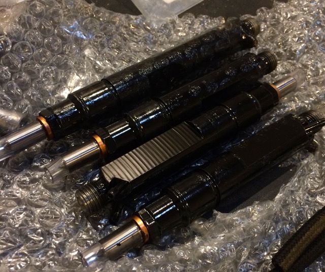
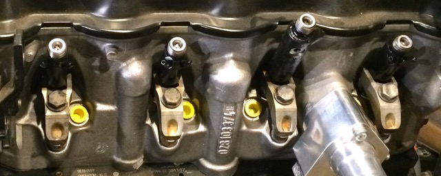
| − | + | Four injectors with DLC764 nozzels from [http://www.kermatdi.com KermaTDI] | |
| − | + | [[File:1zAHU-injectors.jpg]] | |
| − | + | Next I usually install the #3 injector first. This will be the only one with a screw hole on the side. It should fall into place, makes ure not to scratch the nozzle! | |
| − | + | [[File:1zAHU-LB-injector-install.jpg]] | |
| − | + | All four injectors installed | |
| − | [ | + | [[File:1zAHU-LB-all-injectors-installed.jpg]] |
| − | + | Once the injectors are in it's time to install the spacer & holder. | |
| − | + | First the spacer goes in like this. You can see the bevel should face up as the way I am holding it | |
| − | + | [[File:1zAHU-LB-injector-028-103-316A-spacer.jpg]] | |
| − | + | Here's the holder bolt, it goes in like this orientation. The curved part of the washer faces down | |
| − | [ | + | [[File:1zAHU-injector-holder-bolt.jpg]] |
| − | + | Here's the holder installed with the injectors | |
| − | + | [[File:1zAHU-injector-holder.jpg]] | |
| − | + | At this point you can install the banjo, banjo bolt, and banjo washer/oring for injector #3. The washer/o-ring goes towards the injector hence, in the orientation I have it held, it'd fall off the bolt. | |
| − | + | [[File:AHU injector 3 banjo.jpg]] | |
| + | |||
| + | Now that the injectors are in, it's the best time to [http://www.vanagondiesel.info/index.php/MTDI_AHU_Conversion_Notes#Glow_Plug_Install install the glow plugs] | ||
| − | + | Once, the glow-plugs are in, install the injector lines and tighten snug with a 17mm | |
| − | + | [[File:1zAHU-injector-lines-installed.jpg]] | |
| − | + | ==== Glow Plug Install ==== | |
| − | + | ===== Reference ===== | |
| − | + | :* [http://www.vanagondiesel.info/index.php/MTDI_AHU_Conversion_Notes#Glow_Plug_Goodies this wiki] | |
| − | + | :* [http://etka.cc/vw/part_single/catalog/vw/markt/USA/modell/PA/year/1997/drive_standart/147/hg_ug/971/subcategory/971011/part_id/0/lang/e ETKA wiring set 97' Passat] | |
| − | + | :* [http://forums.tdiclub.com/showthread.php?p=483553 TdiClub - Glow Plugs 101] | |
| − | + | ===== Tools ===== | |
| − | + | *10mm deep socket | |
| − | + | ===== P/Ns ===== | |
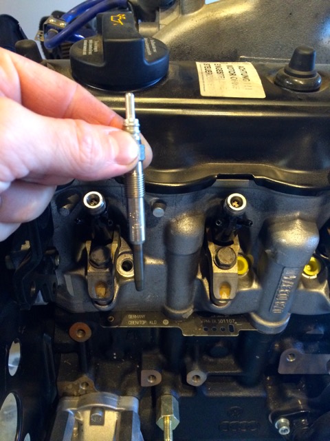
| − | + | : 028971766 - VW Early TDI 2 Wire Glow Plug Harness (’96-01) | |
| − | + | : 0250202022 - VW 1Z AHU ALH TDI Bosch OEM Glow Plug Set ('96-03) | |
| − | + | ===== Photos ===== | |
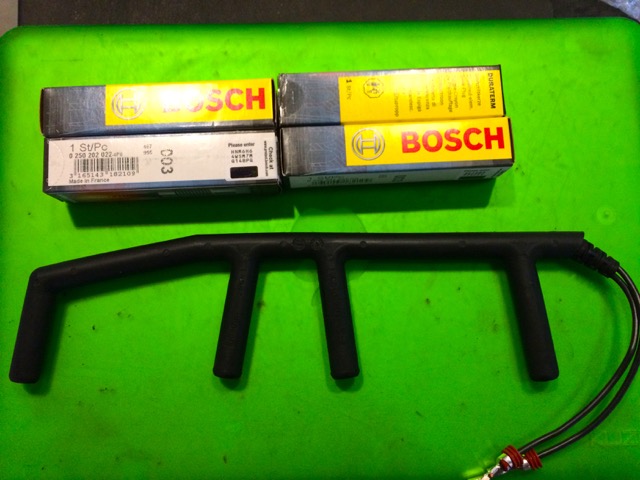
| − | + | Harness with new glow-plugs | |
| − | [[File: | + | [[File:1zAHU-GP-harness.jpg]] |
| − | + | Orientation the glow-plug goes into the block | |
| − | + | [[File:1zAHU-GP-orientation.jpg]] | |
| − | + | Glow Plug Assembly installed (wire goes towards the clutch) | |
| − | [[File: | + | [[File:1zAHU-GP-installed.jpg]] |
| − | + | ==== Coolant Pump to Block Coolant Flang Hose ==== | |
| − | + | It may seem like an odd place to put this, but it's wise to install this hose first before putting on the IP. The IP will be a blocker to a point. | |
| − | + | Hose # 3237850012 | |
| − | + | With my custom coolant flange, I needed to trim about 3/4" an inch off to have it fit, but in the end it'll look like this. | |
| − | + | [[File:AHU IP Mounting Bracket.jpg]] | |
| − | + | ==== Diesel Injection Pump Mounting ==== | |
| − | ===== | + | ===== References ===== |
| − | [ | + | :* [http://etka.cc/vw/part_single/catalog/vw/markt/USA/modell/PA/year/1997/drive_standart/147/hg_ug/130/subcategory/130020/part_id/3686606/lang/e ETKA -Injection Pump Mounting] |
| − | + | ===== P/Ns ===== | |
| − | + | : 1 x 028130147B - Injection Pump Bracket | |
| − | + | : 3 x N10226004 | |
| − | : | + | : 3 x N01224110 |
| − | : | + | : 2 x N0111849 @ 25Nm |
| − | : | + | : 1 x 068130173B - arm |
| − | + | : 1 x 068130174 - arm | |
| − | + | : 1 x N90477301 | |
| − | + | : 1 x N01033512 @ 25Nm | |
| − | + | : 1 x N0110212 | |
| − | + | : 1 x 068130199 | |
| − | + | : 1 x 068130197 @ 25Nm | |
| − | + | ===== Tools ===== | |
| − | + | :* Blue Thread Locker | |
| − | + | :* H6 | |
| − | + | :* 10mm wrench | |
| − | + | :* 22mm socket | |
| − | + | :* Universal Sprocket Buster Counterhold Tool | |
| − | + | ===== Photos ===== | |
| − | + | Main bracket mounted to the block with the three bolts | |
| − | [ | + | [[File:AHU IP Mounting Bracket.jpg]] |
| − | + | Set the IP into it, you'll see the front holes line up with the two holes. | |
| − | + | Once per the video for the IP arm installation to the engine is complete you need to install the rear bolts from ETKA #13,14,16,17,5 | |
| − | + | This photo shows where they install: | |
| − | + | [[File:AHU IP Mounting Bracket-backbolt.jpg]] | |
| − | + | The bolt should be setup like this: | |
| − | + | [[File:Rear-IP-bolt-install.jpg]] | |
| − | + | And go in the back like this: | |
| − | + | [[File:Rear-IP-bolt-install-b.jpg]] | |
| − | + | Now the plug-nut which is this: | |
| − | + | [[File:068130197-plug-nut.jpg]] | |
| − | + | Now install with the orientation shown here @ 25Nm | |
| − | + | [[File:068130197-plug-nut-install.jpg]] | |
| − | + | The Bosch VE / Cummings 4BT Injection Pump installed! | |
| − | [ | + | [[File:MTDI AHU IP Installed.jpg]] |
| − | + | ===== Videos ===== | |
| − | + | The mounting arms of on the IP #6 & #7 on the ETKA reference page can be confusing so here's a video on it: | |
| − | [https:// | + | [https://www.youtube.com/watch?v=YEX8eEr0Iio&feature=youtu.be Youtube Video of IP Arms] |
| − | [ | + | [https://www.youtube.com/watch?v=-2ljJDWeXcY&feature=youtu.be Youtube Video of IP Arm installation to engine] |
| − | ==== | + | ==== Diesel Injection Lines Install ==== |
| − | + | ===== P/Ns ===== | |
| − | + | TDI AHU Steel Injector Fuel Lines - 028130301M/2M/3N/4N Injector Lines | |
| − | + | Two sources I found new: | |
| − | [http://www. | + | [http://www.hansautoparts.com/028130301MInjectorLines.aspx Hans AutoParts] |
| − | + | [https://www.partsplaceinc.com%2Fproducts%2Fproduct-detail.aspx%3Fsku%3D17275&usg=AFQjCNG-7ZVAjPWph9pgg7s8bacJ5akbGQ&sig2=ztaGfRWi_g-cUonbzUH1mA PartsPlace Inc] | |
| − | + | So, this is the one thing of my install, that wasn't as straight-forward. With the larger pump, I had to bend my lines a tad. This MAY not be required for another type of pump. I believ the 4bt delivery valves too long. Find some for an etdi pump. | |
| − | |||
| − | |||
| − | + | ===== Photos ===== | |
| − | + | [[File:AHU Injector lines installed.jpg]] | |
| − | + | ==== Diesel Injection Pump Sprocket Install ==== | |
| − | ===== | + | ===== Reference ===== |
| − | + | :* [http://etka.cc/vw/part_single/catalog/vw/markt/USA/modell/PA/year/1997/drive_standart/147/hg_ug/130/subcategory/130020/part_id/3686606/lang/e ETKA -Injection Pump Mounting] | |
| − | + | ===== P/Ns ===== | |
| − | : | + | : 1x 028130111A - toothed belt pulley |
| − | + | : 1x N0127102 - woodruff key | |
| − | + | : 1x N0122333 - washer | |
| − | : | + | : 1x N0110212 |
| − | + | ===== Tools ===== | |
| − | : | + | :* torque wrench |
| − | + | :* 22mm socket | |
| − | + | :* Blue Thread Locker | |
| − | : | + | :* Universal Sprocket Buster Counterhold Tool |
| − | + | ===== Photos ===== | |
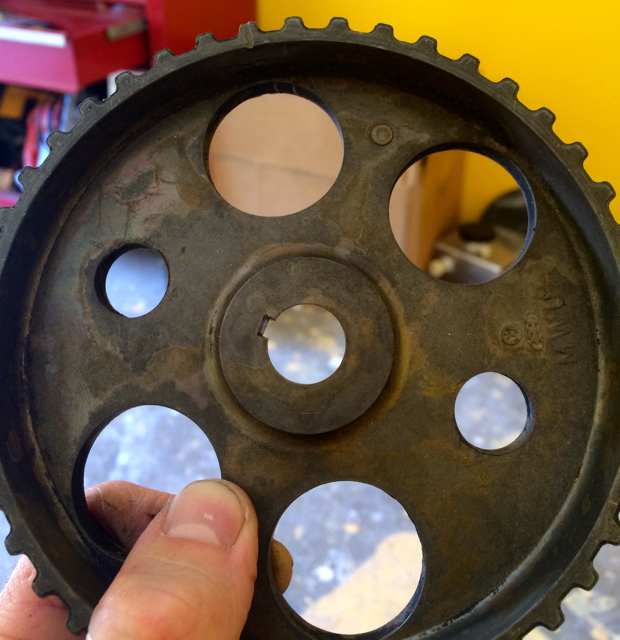
| − | : | + | Install the toothed pulley where any VW markings face towards you. The orientation should be like this: |
| − | + | [[File:AHU mTDI IP toothed pulley.jpg]] | |
| − | + | Installed: | |
| − | + | [[File:AHU mTDI IP toothed pulley installed.jpg]] | |
| − | + | ==== Injection Pump Idler Pulley ==== | |
| − | + | ===== Reference ===== | |
| − | |||
| − | : | + | :* [http://etka.cc/vw/part_single/catalog/vw/markt/USA/modell/PA/year/1997/drive_standart/147/hg_ug/130/subcategory/130020/part_id/3686606/lang/e ETKA 1997 Passat Engine] |
| − | + | ===== P/Ns ===== | |
| − | + | : 1 x 028109244B - Idler Pulley | |
| − | : | + | : 1 x N0147172 - bolt |
| − | + | ===== Tools ===== | |
| − | + | :* torque wrench | |
| − | : | + | :* Blue Thread Locker |
| − | + | :* H6 | |
| − | + | ===== Photos ===== | |
| − | : | + | Installed: |
| − | + | [[File:IP Idler Pulley.jpg]] | |
| − | + | ==== Camshaft Sprocket ==== | |
| − | + | Only real note for this is to grease the thick washer that comes with N90502103. It's been noted that some major corrosion can happen. | |
| − | + | I lightly PTFE geased the center of the sprocket where the washer contacts it. I later do a light top coat once the bolt is torqued and installed. | |
| − | + | ===== Reference ===== | |
| − | + | :* [http://etka.cc/audi/part_single/catalog/au/markt/CA/modell/A4/year/1997/drive_standart/156/hg_ug/109/subcategory/109010/part_id/0/lang/e ETKA - AHU Camshaft] | |
| − | + | ===== P/Ns ===== | |
| − | + | 1 x 069109111 - toothed belt pulley (camshaft sprocket) | |
| − | + | 1 x N90502103 @ 75Nm or 55ftlbs; VW states 45Nm / 33ftlbs ; further research appears this has been more problematic on ALH than 1z/AHU engines, but still good to do. | |
| − | + | ====== Tools ====== | |
| − | :* | + | :* Blue Thread Lock |
| − | :* | + | :* PTFE Grease |
| − | :* | + | :* Torque Wrench |
| − | :* | + | :* 18mm socket |
| − | |||
| − | + | Lightly grease of center of camshaft sprocket | |
| − | + | ==== TDC Process ==== | |
| − | + | So, now that you have everything on the engine sides, it's time to get serious about pulleys and belts. | |
| − | + | This will walk through TDC of all but the flywheel. It's good practice for the n00b! | |
| − | + | When you install the flywheel and TDC that, you'll want to make sure everything else is at TDC and then tighten the timing belt. It'll happen soon. | |
| − | + | ===== References ===== | |
| − | + | VW; W42-011-294-103B | |
| − | + | Bentley; 23b-5 through 23b-9 p13-14 to 13-26 | |
| − | + | [https://www.youtube.com/watch?v=UGgJaWzjCSk VWDiesel.net Youtube via Ryan Turner] | |
| − | [ | + | [http://www.myturbodiesel.com/wiki/timing-belt-replacement-mk3-vw-jetta-vw-passat-tdi-removal/ MyTurboDiesel AHU timing belt removal] |
| − | + | [http://www.myturbodiesel.com/wiki/timing-belt-installation-vw-jetta-tdi-ahu-engine-and-vw-passat-1z/ MyTurboDiesel AHU timing belt installation] | |
| − | + | ===== Tools ===== | |
| − | + | 19mm socket | |
| − | : | + | [http://www.metalnerd.com/cat03.htm MetalNerd B4/mkIII timing beltnDeluxe kit] |
| − | + | VW Specialty tool Diesel Timing Tool (Gauge Holder) 2066 | |
| − | + | Dial Gauge | |
| − | + | ===== Ground Zero (TDC) ===== | |
| − | + | From a knowledgable person; Michael Courtenay on the Diesel Powered Vanagon FB group | |
| − | + | "You can only verify TDC with the cam or injection pump after the engine is timed and the belt is on. | |
| − | + | Obviously if you have no belt you cannot verify that #1 is at the top by anything other than the crank. Without a belt the cam and crank can move out of phase with one another, so you need a way to confirm each of them independent of one another, hence the plate, pin, and crank tool. | |
| − | + | The Metalnerd crank pulley tool bolts to the face of the crank sprocket (with harmonic balancer removed, but with the crank bolt in place). The face of the sprocket has four M8 bolt holes. The holes are not in a perfect square, so the tool only bolts on one way, or 180 degrees out from that way. That would be with #1 at TDC or with #4 at TDC. Those two travel together on the crank though, and 2 & 3 travel together. In practice it doesn't matter which way it fits if the engine is not timed yet, because that then becomes #1 TDC. | |
| − | + | Any marks on the dampener or flywheel are secondary and can be used to check crank position once the engine is in the vehicle. They are not necessary if you have the tool. | |
| − | + | The tool does come with the Deluxe set. It is a round piece of metal with an ear bent perpendicular to it. If you hold it up to the crank sprocket it will be immediately obvious how it fits. | |
| − | + | You can also check for TDC by dropping the oil pan and verifying that the piston is all the way up. | |
| − | + | The notch on the rear of the camshaft is cut off-center so the locking plate will only fit into place when the #1 valves are in the correct position." | |
| − | + | '''HOWEVER''', you WILL want to recheck TDC after you mount the flywheel. This will though get you used to checking TDC on the Crank, IP, & CamShaft | |
| − | + | ===== Camshaft ===== | |
| − | + | You need to remove the valve cover | |
| − | + | ====== Photos ====== | |
| − | + | Valve Cover Removed | |
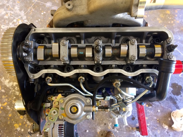
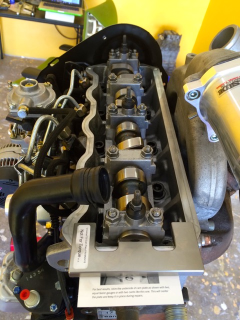
| − | + | [[File:AHU valve cover removed.jpg]] | |
| − | + | CamShaft set to TDC via turning on the sproket end | |
| − | + | [[File:AHU camshaft TDC.jpg]] | |
| − | + | ===== Injection Pump ===== | |
| − | + | ====== Photo ====== | |
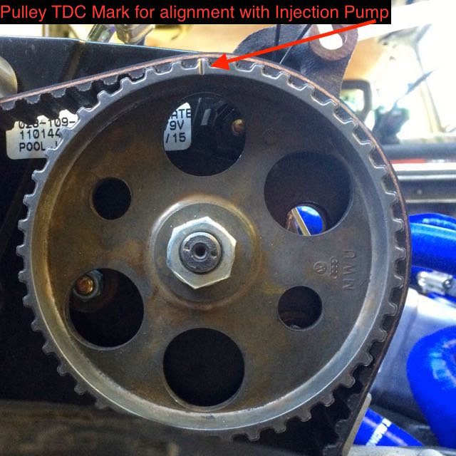
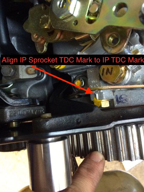
| − | + | Find this mark on your Sprocket | |
| − | [[File: | + | [[File:IP Pulley TDC mark.jpg]] |
| − | + | You'll want to have this TDC mark point to the TDC mark on the Injection Pump casing | |
| − | [[File: | + | [[File:IP Pulley TDC.jpg]] |
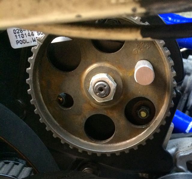
| − | + | Now insert the Injection Pump Locking Tool | |
| − | + | [[File:IP Pulley Lock.jpg]] | |
| − | + | The Injection Pump is now set to TDC! | |
| − | Now | + | Now to time the Injection pump watch the below timing videos to get visual of how it's done. |
| − | + | ====== Videos ====== | |
| − | + | [https://www.youtube.com/watch?v=ajBVYpApGqM AHU Injection Pump Locking Pin You Tube Video] | |
| − | [ | + | Once the belt is one now time the injection pump with [https://www.youtube.com/watch?v=UGgJaWzjCSk Ryan Turner's video] |
| − | == | + | Another IP Timing video is [https://www.youtube.com/watch?v=x5RF6C1OX70&feature=youtu.be this one] |
| − | + | '''NOTES:''' | |
| − | + | :* When you turn CCW of TDC to get the plunger at the lowest point, it may take a quarter turn of the flywheel to get that. It may feel like a whole half turn. When it stops, that's when you want to zero it out. | |
| − | + | :* Press the CCV tube down, it may press on the dial gauge and throw off your reading | |
| − | + | :* Remove the injector lines FROM the injection pump and loosen the ones at the block. This will allow easier fitment of the injector lines after you turn the IP to adjust the timing. | |
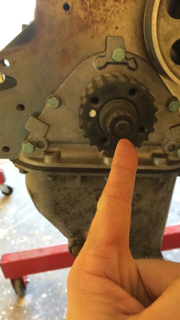
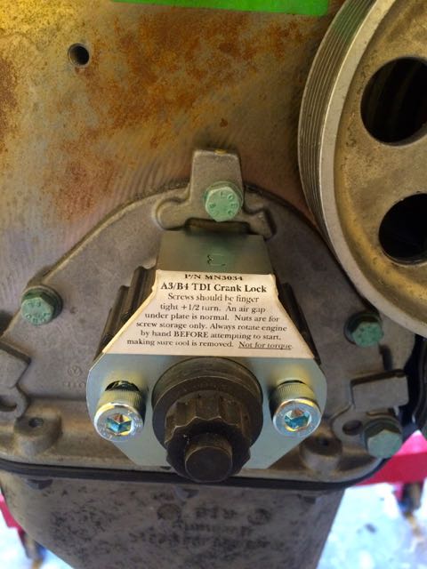
| − | + | ===== Crank ===== | |
| − | + | You need to set the crank to TDC. This is accomplished by turning it till you can set the crank lock tool | |
| − | + | ====== Photos ====== | |
| − | + | You'll want to turn the crank bolt shown below with a 19mm and turn it clock-wise to adjust fitment for the crank lock tool | |
| − | + | [[File:AHU crankshaft bolt.jpg]] | |
| − | + | Crank lock tool will fit on one way and look like the below | |
| − | [[File: | + | [[File:AHU crank lock tool.jpg]] |
| − | ==== | + | ===== FlyWheel / Pressure Plate ===== |
| − | + | ====== Reference ====== | |
| − | [http://www. | + | Go to this [http://www.vanagondiesel.info/index.php/Betsy_Bertha%27s_MTDI_AHU_Conversion_Notes#Marking_new_TDC_on_TDI_Flywheel_.26_Pressure_Plate section] |
| − | ==== | + | ==== Clutch ==== |
| − | + | ===== References ===== | |
| − | + | [http://www.vanagondiesel.info/index.php/Betsy_Bertha%27s_MTDI_AHU_Conversion_Notes#Clutch_2 My wiki notes] | |
| − | + | Get the following to support a full TDI setup | |
| − | + | [http://www.vw-t3-bus-shop.de/en/clutch-dorn/gearbox-input-shaft-tdi-golf-tdi-clutch-conversion-to-org Modified Bernd Jager TDI input shaft] | |
| − | : | + | [http://www.vw-t3-bus-shop.de/en/abdeckblech-zum-schwungrad-aus-edelstahl Bernd Jager TDI flywheel cover plate] |
| − | ===== | + | ===== Betsy's Route ===== |
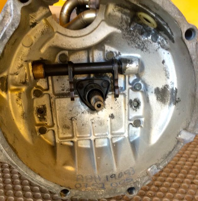
| − | + | I installed a LUK 17-050 DMF Clutch & Flywheel setup. I had to trim the bellhousing to get it to fit properly and able to spin. That's mentioned in the transmission section :) | |
| − | + | ==== Transmission ==== | |
| − | + | I'm starting with an 82' diesel, so I *have* to upgrade my transmission or expect to blow shit up early on. | |
| − | + | I'd love to go 5spd, but not knowing enough to go this route, I have decided on a rebuilt DK (80-82 air-cooled Vanagon transmission). | |
| − | + | Most converting to a TDI should swap out their stock DV transmission for something else. | |
| − | + | ===== Tranny Upgrade Notes ===== | |
| − | + | The TDI will not have any difficulty cruising at 3500rpms or even a bit higher. The only downsides are noise and a bit of a drop in fuel economy. If your preference is to cruise at 65, then gear 3,000 @ 65MPH. With that gearing you will be able to cruise at 70-75MPH if need be and will still be high enough in the rpms @ 65 to develop enough HP for cruising with a 'cushion'. | |
| − | [ | + | "Max torque on a stock TDI is around 2200 RPM. Max hp is around 3800 RPM. The TDI seems happiest in a Vanagon between 2600 and 2800 RPM. You are above the max torque, but well below the max hp. Your gearing and tires will dictate what speed that is." - [http://www.thesamba.com/vw/forum/viewtopic.php?t=403215&postdays=0&postorder=asc&highlight=borla&start=20 Mark Ward - The Samba]. |
| − | + | In this ratio, I would think a Westy would be more the range of 2700-2900rpm to account for the extra weight; ~700lbs last I heard! | |
| − | = | + | Till a better place [http://www.thesamba.com/vw/forum/viewtopic.php?p=7181516 linkage differences here] |
| − | + | Obtained a DK air-cooled transmission | |
| − | + | [http://volksweb.relitech.com/helmut/GEARBOX.HTM VW Gear Ratio] | |
| − | + | [[File:VanagonTransRatios.xls]] | |
| − | + | Here are some good calculators: | |
| − | + | [https://tiresize.com/height-calculator/ Tire Size Calculator] | |
| − | + | [http://spicerparts.com/calculators/transmission-ratio-rpm-calculator Transmission Gear Calculator] | |
| − | + | ===== Betsy's Decision ===== | |
| − | : | + | Since each setup is different for me I decided on the following: |
| − | + | It "is" possible to put a 5spd transmission in the 82' style setup, but you'll be having to play with linkage and the like. I've read of a few who have done it. It was a split down the middle if it was worth the trouble than just going the 4spd. | |
| − | + | For this reason, MOST people who do an 82' diesel conversion just roll with a DK (80-82 air-cooled Vanagon) transmision with a taller 3rd & 4th gear. As it will fit with the diesel vanagon bell-housing attached to it. | |
| − | : | + | [http://www.aatransaxle.com AA Transaxle] - Rebuilder |
| − | : | + | My rebuild included: |
| − | : | + | : 3rd 1.12 |
| + | : 4th 0.70 | ||
| + | : LSD | ||
| − | + | For my tires my RPM ratios look like (215/65/16): | |
| − | + | 4.571 FD @ 0.70 - 2672 @ 65mph | |
| − | + | 4.571 FD @ 0.70 - 2878 @ 70mph | |
| − | + | ===== Transaxle to Engine Mounting ===== | |
| − | ===== | + | ====== Reference ====== |
| − | + | :* [http://etka.cc/vw/part_single/catalog/vw/markt/RDW/modell/T2/year/1982/drive_standart/4/hg_ug/141/subcategory/29000/part_id/3691459/lang/e ETKA Volkswagen Typ 2/syncro 1982, coupling] | |
| − | [ | + | :* [https://www.thesamba.com/vw/forum/viewtopic.php?p=6632114 TheSamba article to read regarding the DK] |
| − | ==== | + | ====== Terms ====== |
| − | + | So, there's a ton of slang in this portion of the engine. Why? I don't know, people must be fucking bored. | |
| − | + | :'''Service Manual''' | '''Slang''' | '''Abbv.''' | |
| − | + | : Clutch Release Bearing | Throw Out Bearing | TOB | |
| − | + | : Needle Bearing | Pilot Bearing | NB / PB | |
| − | + | ====== P/Ns ====== | |
| − | + | These should ideally be replaced if going through the trouble of redoing a transmission: | |
| − | + | : 056105313C = needle bearing | |
| − | + | : 091141165D = clutch release bearing or a more modern p/n 113141165B | |
| − | + | : 016141181 = clutch release bearing guide tube, if needed | |
| − | ===== | + | ====== Mounting Bits ====== |
| − | + | If you're transfering your DV components for the conversion, KEEP your diesel bell housing bolts that go into the engine. | |
| − | + | If you're in Europe you can get the bolts from [https://www.brickwerks.co.uk/t3-d-td-engine-to-bell-housing-bolt-kit.html BrickWerks] | |
| − | : | + | If you're like myself in the USA, and starting with no previous DV parts to work with finding those bolts can be a real PITA. Fortunately, I got an awesome reply from [http://www.thesamba.com/vw/forum/viewtopic.php?p=8140732#8140732 syncroserge] with the following information: |
| − | + | All bolts, no studs. ETKA is both inaccurate and incomplete on this. The starter bolts are in: | |
| + | Electrical Systems, Starter and Single Parts, diesel eng. | ||
| − | + | Bentley 34.15 | |
| − | + | :* transmission to engine bolts/nuts 30Nm (22ft lbs) | |
| + | :* drive shafts to transmission 45Nm (33ft lbs) | ||
| − | + | : 2x M12 x 1,75 x 122mm, N 040 350 1 | |
| − | + | The one on the clutch slave has no washer. | |
| − | + | On the other side of starter washer is: | |
| − | + | : A13 x 24 x2,5 , N 011 531 7 | |
| − | + | For the rest of the block. in Engine, Clutch, look under cylinder block with pistons, oil sump | |
| − | + | Then next 2 are: | |
| − | + | : M12 x 1,75 x 80mm, N 010 464 4, both with same washer as above. | |
| − | + | At bottom of block, | |
| − | + | : M12 x 1,75 x 100mm, N 010 458 2, washer same as above, nut: | |
| − | : | + | : M12 x 1,75, N 011 030 4 |
| − | : | + | Two bolts from bellhousing to oil pan (never found those in ETKA): |
| − | : | + | : M10 x 1,5 x 65mm, N 010 465 9, both with washers: |
| − | : | + | : A10,5 x 21 x 2, N 011 527 11 |
| − | ===== | + | ===== Clutch Cross Shaft Installation ===== |
| − | + | The transmission didn't have a Cross Shaft when sent to AA, so we need to install one. | |
| − | : | + | There are two available Cross Shafts that you can get from Weddle: |
| − | :* | + | :* [https://weddleindustries.com/product/1000897 091-141-701HD] |
| − | :* | + | :* [https://weddleindustries.com/product/1000895 091-141-701] |
| − | + | I went with the HD after reading about a Subaru H3 using it and others saying it's beefier than the OE from their visual inspection. | |
| − | + | You'll also want parts | |
| − | + | :* 1x [https://weddleindustries.com/product/1001308 113-141-165BS] - Throw Out Bearing (TOB) | |
| − | :* [ | + | :* 1x [https://weddleindustries.com/product/1002182 113141707C] - HEAVY DUTY 20MM BRONZE CLUTCH CROSS SHAFT BUSHING (OIL IMPREGNATED) |
| − | :* [ | + | :* 1x [https://weddleindustries.com/product/1001319 113-141-711A] - THIN BUSHING FOR 20MM CLUTCH CROSS SHAFT, GENUINE VW |
| − | + | :* 1x [https://weddleindustries.com/product/1001321 113-141-717A] - 20MM WASHER FOR LATE CLUTCH CROSS SHAFT, NEW | |
| − | + | :* 1x [https://weddleindustries.com/product/1001382 113-311-141A] - LOCATING BOLT, 14MM LONG, NEW | |
| − | + | :* 2x [https://weddleindustries.com/product/1004112 N-012-420-1] - CIRCLIP FOR VW CLUTCH CROSS SHAFT, LATE (20MM) | |
| − | + | Lightly grease the bushing and teeth of the shaft when installed without the TOB it'll look like: | |
| − | + | [[File:Betsy Clutch Cross Shaft.jpg]] | |
| − | + | Now, we're ready to install the TOB. Use a light coast of grease inside the TOB where it slips over the shaft. Make sure to slide it over in this orientation and then use a flat head screw-driver to pry the springs around the hooks: | |
| − | [[File: | + | [[File:Betsy TOB Install.jpg]] |
| − | + | Installed | |
| − | + | [[File:Betsy TOB Installed.jpg]] | |
| − | + | ===== Marking new TDC on TDI Flywheel & Pressure Plate ===== | |
| − | + | To be able to get TDC set on the CrankShaft using the FlyWheel, the engine now needs to be removed off the stand and lowered. | |
| − | + | [[File:Betsy AHU lowered to ground.jpg]] | |
| − | + | This is where things get interesting. | |
| − | + | I'm using the TDI input shaft, which means using a TDI clutch & flywheel. In my-case the LUK 17-050 DMF which has the flywheel/PressurePlate already attached. | |
| − | + | In my setup there's going to be two hurdles: | |
| − | + | :* Making clearance for the DMF flywheel with the diesel bell-housing | |
| − | + | :* Getting the proper TDC mark on the TDI Flywheel. | |
| − | + | First cover the input shaft and Clutch Cross Shaft with masking tape. Then do a light spray of white spray paint inside the bell-housing. A very light spray. Then let that dry. | |
| − | + | The Diesel Vangon Flywheel & Pressure plate have what you need to do this. The Pressure Plate will have a '''V''' indicating where TDC should be set | |
| − | + | [[File:DV FLYWHEEL TDC MARK.jpg]] | |
| − | + | Now, I installed the DV pressure plate & flywheel to the AHU engine. Here's a photo of the flywheel installed (forgot to do one with the PP on it). Remember the PP showen above has the '''V''' which is what we want to get TDC of the Crank Shaft | |
| − | + | [[File:DV Flywheel on AHU.jpg]] | |
| − | I | + | Now, this is where I had a problem, and thanks to my friend Kim Mohr who gave a solution. When turning the crank to adjust to the DV TDC mark, I kept hitting a valve. I ended up having to lossen the camshaft studs and adjust it when doing the flywheel TDC mark. Then I tightend the studs back to torque spec from the Bentley. I then turned it a few times to make sure it cleared and had a few full rotations of the crank. I wish I had taken photos during this procedure, but it was a spur of the moment figuring with two others. So, a bit hectic. |
| − | + | You'll at this point when the crank turns freely you'll want to mount up the DMF flywheel to the engine. Then mount up the tranny with the Bell Housing to the engine. | |
| − | ' | + | Once that's mated, try turning the crank. You "should" have interference. Go Clockwise till it stops then go CCW till it stops. Do this a few times. |
| − | + | Now remove your transmission & bell-housing. | |
| − | + | You should see where the paint was rubbed indicating where to trim with a grinder to let the flywheel clear | |
| − | [[File: | + | [[File:DV BH Paint scratch TDI flywheel.jpg]] |
| − | + | Trim and remount and make sure it rotates cleanly. | |
| − | + | Then remove the transmission and the DMF clutch/flywheel and put the DV flywheel/PP back on the engine. | |
| − | + | Now mate up the transmission again so you have the BH mark for the Flywheel/PP. Turn the crank till you have TDC of the flywheel, then install your crank-lock tool from MetalNerd. | |
| − | + | At this point TDC the IP and CamShaft as indicated above. | |
| − | + | Once, everything is at TDC; crank, camshaft, and IP | |
| − | + | You can now remove the DV flywheel/pressure plate | |
| − | + | At this point you should install the pilot bearing lightly greased tapped into the spot on the engine | |
| − | + | Install orientation | |
| − | + | [[File:DV pilot bearing.jpg]] | |
| − | + | Installed | |
| − | + | [[File:DV pilot bearing-installed.jpg]] | |
| − | + | Install the TDI DMF Clutch/Flywheel. | |
| − | + | [[File:LUK-DMF-mounted-Betsy.jpg]] | |
| − | + | Reinstall the transmission with the bell-housing. | |
| − | + | Now, the BH will give a TDC mark of where the DV was that you now mark on your TDI DMF Flywheel/PP as indicated below; | |
| − | + | [[File:LUK-DMF-TDC-mark.jpg]] | |
| − | + | Now, it's time to install the engine! Got your crew? I got mine! | |
| − | + | [[File:Betsy install crew.jpg]] | |
| − | + | Ready to install the engine! | |
| − | [[File: | + | [[File:Betsy ready to mount.jpg]] |
| − | + | ===== Transmission Mount ===== | |
| − | [ | + | This is the best time to install a [http://www.t3technique.com/suspension-bushings/powerflex-suspension-bushings/2wd-gearbox-mount-bushing.html T3 Transmission Mount (74mm)] |
| − | + | There is NO easy way to remove the old bushing. I drilled holes, sawed, cut, etc. I eventually got the damn thing out. You'll want the end result like this: | |
| − | + | ====== Photos ====== | |
| − | + | Inner ring removed | |
| − | [[File: | + | [[File:DV TransMount Inner Ring Removed.jpg]] |
| − | + | Installed | |
| − | + | [[File:T3 DV TransMount Installed.jpg]] | |
| − | + | ===== Clutch Slave Cylinder ===== | |
| − | + | I replaced my Clutch Slave Cylinder while I was swapping the tranny out. I figured it was a smart move. It's [http://www.van-cafe.com/home/van/page_690_664/clutch-slave-cylinder.html P/N 251.721.263 and available at Van-Cafe] | |
| − | + | Removing the old slave-cylinder can be a real PITA. Removing the line from the cylinder even more so! Use a torch on the flar nut, let it cool spray penetrating oil, and repeat a few times tapping the flare-nut with a hammer. Eventually it'll come off OR do the flare-nut on the other end of the line. | |
| − | + | [[File:SlaveCylinderRemoval.jpg]] | |
| − | + | ==== Turbo Oil Feed Line (Turbo to Oil Filter) ==== | |
| − | + | I obtained my K14 turbo Feed Line to Oil Return from DarkSide Developments | |
| − | + | [http://www.darksidedevelopments.co.uk/products/darkside-braided-oil-feed-line-for-1-6-1-9-td.html darkside-braided-oil-feed-line-for-1-6-1-9-td] - which is 12mm on both ends with a banjo | |
| − | ==== | + | ==== Turbo Oil Return Line to Block ==== |
| − | + | Ideal drainage is 12pm in and 6pm out. | |
| − | [ | + | I'm using a 5/8" AN Push Lock hose barbs & hose. Check temperatures! I got [http://ph.parker.com/us/15551/en/push-lok-plus-high-temperature-multipurpose-hose-836 Parker 836] rated to 302. |
| − | + | Use Quality (brass, steel) fittings over aluminum if possible. I had two aluminum snap with a little torque to tighten. Areoquip is a good brand overall. | |
| − | + | When you don't use the AAZ exhaust manifold, you generally tap to the oil pan for the oil-return instead of going into the AHU block. | |
| − | + | Since, we have an AAZ exhaust manifold, we're going to do it right into the block. | |
| − | + | ===== Reference ===== | |
| − | + | :* K14 oil drain to block port size/thread M16x1.5, but I have heard also M18x1.5. The block end is M18x1.5 | |
| − | + | On the K14 you'll only be able to get to 5:45pm on the clock and not 6pm, but it will be good enough to work. | |
| − | + | ===== Parts ===== | |
| − | + | :* M16x1.5 to AN 10 (the metric side should have a crush washer) | |
| − | + | :* M18x1.5 to AN 10 (the metric side should have a crush washer) | |
| − | + | :* AN 10 Female 45deg 5/8th Push Lock Hose Barb | |
| − | + | :* AN 10 Female straight 5/8th Push Lock Hose Barb | |
| − | + | :* AN 5/8th Push Lock Hose | |
| − | [ | + | :* M16x1.5 spacers found [ https://www.ebay.com/itm/331929258573?ul_noapp=true M16x1.5 spacers] use crush washers on the metric ends! |
| − | + | ===== Photos ===== | |
| − | + | This is a view from behind the line on the engine to see it's horizontal flow | |
| − | + | [[File:Betsy-v1.0-oil-return.jpg]] | |
| − | + | The below photo shows the spacers. It was still dirty when test fitting with loose. You have to clock the turbo so it clears the exhaust to install the spacers. When you get them tight position horizontal with the exhaust manifold it's near. When you reclock the turbo, if it some how backs out, it'll only do it about 1/8" a turn and hit the exhaust manifold. Kinda a slight fail-safe instead of it pouring out. | |
| − | + | [[File:Betsy-v1.0-oil-return-b.jpg]] | |
| − | + | Here are some photos of the spacers | |
| − | [[File: | + | [[File:M16x1.5-spacer.jpeg]] |
| − | + | ==== Harmonic Balancer & Lower Belt Guard ==== | |
| − | + | Everything about this is pretty straight forward except two things. | |
| − | + | 1.) The bolt for the left bottom is wrong in the ETKA. It should be the one listed below. It's slightly longer than the other M6 | |
| − | + | 2.) The T bolt is a bit confusing, but it just goes through the hole on the WP and locks into place on the lower guard. You'll see by the photos. | |
| − | + | ===== Reference ===== | |
| − | + | :* [http://www.oemepc.com/vw/part_single/catalog/vw/markt/USA/modell/PA/year/1997/drive_standart/147/hg_ug/109/subcategory/109060/part_id/3685900/lang/e ETKA - Passat 1997, toothed belt toothed belt guard 1.9ltr. diesel eng.: AAZ,1Z,AFN] | |
| − | + | ===== P/Ns ===== | |
| − | :* | + | :* 1 x 028-105-243T - Harmonic Balancer |
| − | :* | + | :* 4 x N90-348-706 - bolt M8x45 @ 25Nm / 18ftlb |
| − | + | :* 1 x N90053401 - t-head screw M6X35 | |
| − | + | :* 1 x N01021527 - hexagon bolt M6X15 (this part also comes up often as N01021533) @ 10Nm / 7ftlb ; I would just tighten till snug | |
| − | + | :* 1x N01021226 - hexagon bolt M6X12 @ 10Nm / 7ftlb ; I would just tighten till snug | |
| − | + | :* 1x N01100624 - hexagon nut M6 @ 10Nm / 7ftlb ; I would just tighten till snug | |
| − | + | :* 2 x N0122265 - spring washer | |
| − | ===== | + | ===== Tools ===== |
| − | + | Blue thread locker; use a very light coating on the bolts | |
| − | + | 10mm (socket/driver) | |
| − | + | H6 | |
| − | + | ===== Photos ===== | |
| − | + | How it'll look installed - mock-up | |
| − | + | [[File:AHU lower belt guard.jpg]] | |
| − | + | ==== Engine Carrier Bars & Brackets ==== | |
| − | + | Ah carrier bars. So, there's the 82' style which was an one-off in the USA and then 83+ which was when the engine got pushed back roughly 2" towards the rear to accomodate for a longer WBX transmission. | |
| − | + | When you have an 82' diesel, it make sense to keep that arrangement. It's also been argued by some the 82' style allows easier access for working on the engine, as it's not 2" closer to the rear. | |
| − | + | ===== Upgraded 82' Bars ===== | |
| − | + | It's known that the 82' bars provide more vibration which some will argue. Myself when I researched the interwebz the general consensus was that they are not as good with vibrations compared to the newer 83' style carriers. Most people don't even notice a real difference. However, with my physical health, I will do whatever I can to make it more comfy. | |
| − | + | Also, the cross-member that connects the two carriers that goes over the oil-pan is a very weak link. I have read where others have used a stonger tube bar to help it from twisting over. Because the 83' carriers don't have the rubber bushings on the ends there's no requirement for the cross member bar. | |
| − | + | That said, I went with 83' style bars, but just not ANY 83' bars though, Tony @ TSI-Engeering found on [http://www.thesamba.com/vw/classifieds/search.php?username=91Transporter16%22 TheSamba] makes. He also makes a 50' degree DS mount to clear the turbo. I didn't realize that when I bought my DS mount. | |
| − | + | I got a set of his 83' 2WD Carrier bars and then moved the motor brackets (had him lightly mark them where he installs) and then moved it towards the front of the van 2". It mounted perfectly! | |
| − | [ | + | I then installed his [http://www.thesamba.com/vw/classifieds/detail.php?id=1382462 Isolator Mounts] which use VW P/N 357199402BMY (Meyle has a better fitment with the isolator bracket I've read). |
| − | + | This allows for a more modern and easily found engine mount; searches will present it as a motor/transmission mount. It appears it was more widely used as a transmission mount. | |
| − | + | ===== Reference ===== | |
| − | + | :* [http://etka.cc/vw/part_single/catalog/vw/markt/USA/modell/VA/year/1982/drive_standart/4/hg_ug/199/subcategory/30010/part_id/3686931/lang/e ETKA - 82' engine brackets bonded rubber bush F >> 24-C-175 000 1.6ltr. DIESEL:CS] | |
| − | + | :* [http://www.thesamba.com/vw/forum/viewtopic.php?t=496589 TheSamba - '82 vs. '83 diesel engine carrier bar differences] | |
| − | + | :* Tony @ TSI Engineering 2WD Carrier Bar Reference Document | |
| − | + | [[File:TSI Engineering Carrier Bar Install Doco.jpg]] | |
| − | + | ===== TSI Carrier Install ===== | |
| − | + | Bars Installed | |
| − | + | [[File:TSI Eng carrier installed.jpg]] | |
| − | + | Bracket View | |
| − | [[File: | + | [[File:TSI Eng carrier-mount-b.jpg]] |
| − | + | Front Carrier Mount (no rubber!) | |
| − | + | [[File:TSI Eng carrier-mount.jpg]] | |
| − | + | ===== P/Ns ===== | |
| − | ===== | + | ====== Driver Side Mount ====== |
| − | + | This has a little more 'wiggle' room with part variations | |
| − | + | There's essentially two washers and one bolt per mounting point (4 mounting points). | |
| − | + | :* 4x N01024222 (M8X25) or N0102478 (M8X35) based on fitment | |
| − | + | :* 4 x N01224111 - spring washer | |
| − | + | :* 4 x N01152520 - washer | |
| − | + | :* 1 x N10155207 - M10 nut | |
| − | ===== | + | ====== Passenger Mount ====== |
| − | + | :* 3 x N0102584 - bolt | |
| − | + | :* 3 x N0122422 - washer | |
| − | + | :* 3 x N01152711 - spring washer | |
| − | + | :* 1 x N10155207- M10 nut | |
| − | === | + | ===== Driver Side Bracket ===== |
| − | + | If you use a larger turbo you'll need to fabricate a bracket that'll fit it. | |
| − | + | There are options though: | |
| − | I | + | :* [https://epytec.de/de/vw-t2-t3-bus-motorhalter-tdi-1-9l-1z-doka-pritsche-syncro-2wd-1967 EPYTEC 1z conversion mount] - This is what I ended up with. |
| − | [ | + | :* [http://www.thesamba.com/vw/classifieds/detail.php?id=1731371 Tony @ TSI Engineering] - I would have went this route if I knew he made those along with the carrier bars! |
| − | + | ===== Photos ===== | |
| − | + | ====== Driver Side ====== | |
| − | + | Driver Side Stock 82' Diesel Vanagon engine bracket | |
| − | + | [[File:DV driverside engine bracket.jpg]] | |
| − | + | ====== Passenger Side ====== | |
| − | + | Passenger Side Stock 82' Diesel Vanagon engine bracket | |
| − | + | [[File:DV passenger engine bracket.jpg]] | |
| − | + | ==== Relocating Starter Battery ==== | |
| − | + | It became apparent in my setup, that the 82' diesel vanagon battery would need to be moved. I wasn't going to the front passenger, as I have a house battery ther. I also wasn't going to give up my retail under the bench seat. | |
| − | + | Andrew Libby on the forums did this first, but his photo is very poor; however, the idea was to cut above the engine bay right of the transmission. | |
| − | + | ===== Photos ===== | |
| − | + | The initial mark for the hole. I have an Odyssey PC1200 which is smaller than most starter batteries. I don't plan on switching to a different type/brand anytime soon, so that's the measurement I made for my hole. | |
| − | + | My floor had some serious sound deadening added and paint, so yours may look different. | |
| − | : | + | [[File:DV Battery Relocation-a.jpg]] |
| − | + | Hole cut, but a note here. There's four spot-welds that need to be removed to remove the new 'lid'. | |
| − | The | + | The cross member needs to be removed, as it's not structural for anything but helps hold the mat that's above the transmission. It will be in the way of the battery. |
| − | + | [[File:DV Battery Relocation-b.jpg]] | |
| − | + | This is the "new" lid that I'm going to modify. Use some JBWeld to fill in the holes and you'll be good! | |
| − | + | [[File:DV Battery Relocation-c.jpg]] | |
| − | + | NOW to make a box for it! | |
| − | + | ==== Intake & Airbox ==== | |
| − | |||
| − | |||
| − | + | The reason for the starter battery relocation was for the [https://www3.donaldson.com/en/catalogs/engine/033615.pdf Donaldson G065433 air-box] with the bracket p/n H0084412 or H008444 | |
| − | + | I wanted to get the intake routing as direct as possible with my setup. | |
| − | + | Using a passenger fabbed snorkel coming into thje passenger side, putting the Donaldson as shown below, makes it way easier and direct for the hoses. | |
| − | + | '''''NOTE:''''' I had to remove the tabs off the old DV snorkel and those foam bits. It was then able to fit into the passenger side with some wiggling effort with the 3" hose. It WILL go, but be patient and take your time. For securing the hose to the snorkel use Rescue Tape! | |
| − | + | ===== Photos ===== | |
| − | + | Installed view without hoses, yes the clips are functional! The lower is a little bit tight, but it works! | |
| − | + | [[File:Betsy Intake Box-a.jpg]] | |
| − | + | [[File:Betsy Intake Box-d.jpg]] | |
| − | + | This gives some idea of how much hose clearance I'll have. The taillight is installed in the last photo to get a reference: | |
| − | + | [[File:Betsy Intake Box-b.jpg]] | |
| − | + | [[File:Betsy Intake Box-c.jpg]] | |
| − | This is | + | This is the snorkel and 3" hose attached. It was a bit to work the 3" around the snorkel, but it WAS possible! |
| − | : | + | [[File:DV snorkel 3inch tubing.jpg]] |
| − | |||
| − | |||
| − | |||
| − | + | This is the snorkel wrapped with Rescue Tape to attach the hose. This is the BEST tape to use compared to "duct-tape". No substitution for this project! | |
| − | + | [[File:DV snorkel rescued.jpg]] | |
| − | + | This is how the snorkel will look when test-fitting. You'll need to remove the tabs/foam for it to fit | |
| − | |||
| − | |||
| − | + | [[File:DV snorkel moved ps.jpg]] | |
| − | + | Snorkel hose is now attached to the Donaldson as shown in this photo looking in from the rear light | |
| − | [ | + | [[File:Betsy Intake Snorkel Hose Routed.jpg]] |
| − | + | The red one is going to the turbo. It's a tight fit! But it's doable! It's 2.5" on the Donaldson side to 2.25" on the metal pipe | |
| − | + | [[File:Betsy Intake Snorkel Hose Routed-red.jpg]] | |
| − | + | ==== Intercooler ==== | |
| − | + | The Renault 5 GT A2A IC is a good fitting IC for the Vanagon! It's roughly the same size as the SAAB C900, but a tad larger and a thicker core. | |
| − | + | You DO have to modify the van a tad for fitment, but it's a small not noticiable change. | |
| − | + | ===== Modifying the van ===== | |
| − | + | Here is the lip that needs to be folded flat for the IC to fit | |
| − | + | [[File:IC-cuttab.jpg]] | |
| − | + | I marked where to tin-snip with a sharpie. I moved my line further so the two outer lines is where I snipped. | |
| − | [ | + | [[File:IC-test-fit-lines to benb.jpg]] |
| − | + | Here's the IC test fitted with the lip cut and bent outward; later you'll bend it back inward to hold the IC more to the other side of the wall. | |
| − | + | [[File:IC Lip bentout.jpg]] | |
| − | + | Another view of the lip | |
| − | [ | + | [[File:IC Lip bentout-b.jpg]] |
| − | + | ===== Final Test Fit ===== | |
| − | + | Here is a sample fitment. You can go further back than the SAAB thus allowing more of the downward flow into the IC directly. There's still a 45degree roughly out the other side of the IC into the engine bay. Keeping the upper and lower pressure zones fluid. | |
| − | + | [[File:Renault 5GT IC DV Placement.jpg]] | |
| − | + | Here's one from the side | |
| − | + | [[File:IC side fit-b.jpg]] | |
| − | + | ===== Mount & Shroud ===== | |
| − | + | Bent a chunk of steel and made a bolt hole. In the body of the van I made a 8mm X 1.25mm bolt tap. | |
| − | : | + | '''Update:''' I tapped a second bolt hole verticle to stabilize the bracket |
| − | + | [[File:Renault5GT mounted in DV.jpg]] | |
| − | + | There's not much a shroud required! You can put some weather stripping at the top of the area whre the IC mounts, that'll flush the upper area. Near the tail-light entrance, there was a small patch whre upper air could get to the lower area. I used alumnum reflective tape to cover that hole/patch. Very minimal needed for the shroud. The IC fits perfectly there! | |
| − | ==== | + | ==== Intake & IC Routing ==== |
| − | + | '''NOTE:''' | |
| − | + | After driving and revising ignore the sizes in photos and do this for hose sizes; | |
| − | + | Airbox to turbo is 2.25” or 57mm that includes the 2.25”x1”x2.25” tee or better termed “57mm BOV” in ebay. | |
| − | + | Turbo to IC is 2.25” or 57mm and IC to Intake manifold is 2.25” or 57mm | |
| − | + | Here are some photos of how I routed the Intake to the Intercooler | |
| − | + | [[File:IC Intake Routing.jpg]] | |
| − | + | Better view of Intercooler | |
| − | + | [[File:IC Intake Routing 2.jpg]] | |
| − | + | Here are some better detailed photos | |
| − | + | [[File:IC Routing.jpg]] | |
| − | + | '''''NOTE:''''' Get the 57mm (2.25") from the IC to the intake. The turbo inlet is 2.25”, so 2”-2.25” from Donaldson is fine | |
| − | + | And closer to the tee off the turbo | |
| − | [ | + | Tee obtained [https://jagsthatrun.com/products/traditional-hose-tee here] |
| − | + | [[File:IC Routing2.jpg]] | |
| − | ==== | + | ===== Revisions ===== |
| − | + | I kept getting popped hoses off the IC and the joins. I eventually settled on this setup which seems to be a LOT more solid. | |
| − | + | Get two HPS HTSEC90-225-BLUE and trim them down to fit as shown. | |
| − | + | [[File:IC-turbo-hose-routing-revised.jpg]] | |
| − | + | Final result | |
| − | + | [[File:Revised IC Routing.jpg]] | |
| − | ==== | + | ==== Coolant Tank ==== |
| − | + | I wanted to replace the old diesel vanagon coolant tank with something more durable and suitable with the 1.9 engine. | |
| − | [ | + | I got the [http://rockymountainwesty.com Rocky Mountain Westy (RMW)] 1.9 WBX aluminum tank and bracket; they are separate. |
| − | + | ===== Photos ===== | |
| − | + | Here are some photos of my modified install | |
| − | [[File: | + | [[File:RMW 1.9WBX Aluminum Tank.jpg]] |
| − | + | [[File:RMW 1.9WBX Aluminum Tank2.jpg]] | |
| − | + | ===== Coolant Level Sensor ===== | |
| − | + | '''''DO NOT CONNECT''''' | |
| − | This is the DV | + | This is properly hooked up, but WILL NOT work and will make your shit go crazy. Leave the sensor disconnected and use the standard DV setup. You can correct to a later circuit and use the sensor down the road if you wish. |
| − | + | The diesel vanagon to my knowledge in 82' didn't use the coolant sensor wire as shown below. I am NOT sure if the circut on the other end is intact or needs an update for this to work; future project. | |
| − | [ | + | [[File:DV Coolant Level Sensor.jpg]] |
| − | ' | + | However, may as well hook it up to the new tank till you can verify if it works or not. That's half the setup! |
| − | + | The wires are like this. Brown is ground, and the other wire is for the level sensor | |
| − | : | + | [[File:DV Coolant Level Sensor-wires.jpg]] |
| − | + | Hooking up to the new tank would be like this. The ground is connected to the right mounting bolt of the tank. | |
| − | + | [[File:DV Coolant Level Sensor-update.jpg]] | |
| − | == | + | ==== Electrical ==== |
| − | + | ===== Glow Plug Relay ===== | |
| − | + | Mine wasn't mounted properly; the screw tabs were broken off. It was zip-tied to the above wire to hold into place. | |
| − | + | The updated version of this relay holder also moves over the Glow Plug relay fuse. It's integrated. | |
| − | + | ====== P/Ns ====== | |
| − | + | :* 251-937-501B - Relay Holder | |
| − | + | :* 171-911-261E - Glow Plug Relay | |
| − | + | ====== Photos ====== | |
| − | + | This is the relay not mounted against the firewall. I did this for the photo to allow a better view of it. | |
| − | + | Also note, the two TDI glow-plug harness wires are male quick-disconnect ends. The old DV is a spade. What I'm doing is making a "Y" which goes to both TDI Glow-Plug harness wires with female quick disconnects spliced into the old DV glow-plug wire. | |
| − | + | You "could" wire a second relay, since each wire on the TDI harness is for two glow-plugs. That way if you lost one relay you still have two glow-plugs functional. However, it's just as simple to buy a new relay and use the old as a spare relay which is what I did. | |
| − | + | [[File:GlowPlugRelay.jpg]] | |
| − | + | ===== ABF Alternator Plug ===== | |
| − | + | The ABF alternator allows for the connections D+ (alternator excite wire) and W for a future [http://www.vanagondiesel.info/index.php/Misc#Diesel_Cluster_w.2F_tachometer tachometer] hookup. | |
| − | + | The proper plug is a Bosch P/N is 037906240; however, it's only for the plug not the rubber boot & pins. | |
| − | + | [https://www.ecstuning.com/b-bosch-parts/electrical-connector-priced-each/037906240~bos/ ECS Tuning has everything as shown below] | |
| − | + | ====== Photos ====== | |
| − | + | [[File:ABF Alt Plug.jpg]] | |
| − | + | Installed | |
| − | + | [[File:ABF Alt Plug Installed.jpg]] | |
| − | + | ==== Start-up the Engine! ==== | |
| − | + | Once you've replentished the fluids; oil, trans, and coolant. | |
| − | + | At this point, we can start the engine to see if everything worked right! Remember to make '''SURE''' you can crank over the engine manually via the crank-shaft and a 19mm socket! Do it four times to make sure you get TDC at the flywheel each time! | |
| − | + | ===== Bleed air out of the lines ===== | |
| − | + | Use a hand vacuum pump to attach to the Return line port (disconnect the banjo bolt) and suck air through the fuel line with the pump. I used Viton / Tygon hoses for the fuel line. You can get a clear on to see bubbles easy while clearing the air out. | |
| − | + | Then crack open the lines half turn on the injectors. At that point cover with a paper towel or real towel to catch the diesel squirting. Now crank it over about 15sec wait 15sec, then crank again 15sec. Do this till you get only diesel bleeding from the injectors and not air. Once satisified tighten up the 17mm nut on the injectors. Then clean up any diesel that was squirted around. | |
| − | + | Once satisified start her up! | |
| − | : | + | [https://www.youtube.com/watch?v=vLHvmAfyWYU - Betsy's first start!] |
| − | + | ==== Break-In Massaging ==== | |
| − | + | The first 500mi-1000mi will be what you'll find out for any minor tweaking needing for your setup. | |
| − | + | In my case, the wastegate on the turbo was rubbing against my engine bracket on the driver side. I had to remove and trim it a few times to get it happy. | |
| − | + | I also had my inter-cooler rattle on the body a little, where I used some weather stripping to soak up that vibration. | |
| − | + | Also, had one injector line at the IP drip requiring a better bend of it to get it center with the line hole. | |
| − | + | Little things will crop up like this after you start it up. So, don't go driving out of town ASAP. | |
| − | + | Start her up, let her idle a bit, manually let it rev across various spectrums gradually. | |
| − | + | ==== Gauges ==== | |
| − | + | I installed standard VDO gauges, but starting to look at [http://www.speedhut.com/about-speedhutgauges.html SpeedHut] the 90 degree sweep is nice. | |
| − | + | My initial gauge cluster will be this above the OEM cluster | |
| − | : | + | [[File:Betsy Gauges.jpg]] |
| − | + | ===== Wiring ===== | |
| − | + | Piggy back power & ground wires. The senders will come in through the wire loom under the van | |
| − | : | + | [[File:Betsy Gauge Wiring.jpg]] |
| − | + | ===== EGT ===== | |
| − | : | + | Get the [http://www.aircraftspruce.com/catalog/inpages/micro1pyroprobes.php AirCraft Spruce 1/8" NPT Probe] |
| − | + | The VDO gauge would be 310-151 | |
| − | + | ===== Boost ===== | |
| − | + | VDO Gauge 150-104 | |
| − | + | ===== Oil Pressure ===== | |
| − | + | Get the VDO Sender; VDO 360-006 Sender for 80 PSI Oil Pressure Gauge | |
| − | + | ===== Oil Temperature ===== | |
| − | + | Get the Oil Temp Sender VDO 323-423 which is a 300F sender | |
| − | + | Then tap that into your ignition yellow/black wire at your steering console. | |
| − | + | == The Little Things == | |
| − | + | This is where I added an extra dab of customization. | |
| − | + | === Oil Filler Tube === | |
| − | + | So, many like using the dipstick from an 83' style setup, and just filling via the oli-filler tube. | |
| − | + | I wanted to keep the 82' DV Setup, since I prefer it. | |
| − | + | I had the plastic tube made into aluminum (the rest are long gone) because that plastic tube breaks and is NLA. | |
| − | : | + | If interested in a similar tube that utiilizes your existing oil-filler funnel & cap contact [https://www.yelp.com/biz/guyer-machine-shop-hancock Steve @ Guyer Machine Shop] and mention you'd be interested in the aluminum oil-filler tube made for William & Ralph. He'll know what you mean. |
| − | + | With the below tube you only need to replace the O-ring at the tube & elbow if you like; p/n N90090501 or 44X3,5 | |
| − | : | + | [[File:82DVOilTube-a.JPG]] |
| − | + | It uses the plastic telescoping funnel too! | |
| − | + | Installed | |
| − | : | + | [[File:AHU DV oil tube.jpg]] |
| − | + | === AHU Dipstick Plug === | |
| − | + | Plugged the AHU dipstick hole with this | |
| − | : | + | [[File:AHU dipstick plug.jpg]] |
| − | : | + | [[File:AHU-dip stick plug.jpg]] |
| − | + | The magic happened from my friend William Roberts! Slick stuff he can make! | |
| − | + | === Airbox & End Heater Flange Connector === | |
| − | + | All the hoses I got were silcone. | |
| − | + | ==== eBay ==== | |
| − | : | + | On [www.ebay.com eBay] I got the following: |
| − | + | :* 3 Inch Adjustable Multi-Flexible Car SUV Turbo Cold Air Intake System Hose Pipe; snorkel to intake box which was about 4ft I think | |
| − | :* | + | :* 1x 2.5" 90° DEGREE ELBOW; connected to Donaldson intake line |
| − | :* | + | :* 1x 2" TO 2.5" 90 DEGREE ELBOW; connected to donaldson out line to engine |
| − | + | ==== HPS Silicone Hoses ==== | |
| − | + | The following were obtained from [http://hps-siliconehoses.com HPS Silicone Hoses] | |
| − | + | This hose reducer is for the end of the cylinder head where the 5/8" hose goes into a 1" barb. Many will "squeeze" the 5/8" onto the 1" which is a BAD idea. You're likely to split the hose at some point. I actually helped a couple in their conversion in a diesel vanagon with this exact problem. Get the reducer! | |
| − | + | :* HTSR-062-100-BLK ; HPS High Temp 5/8" > 1" ID x 3" Long 4-ply Reinforced Silicone Reducer Coupler Hose Black (16mm > 25mm ID x 76mm Length) | |
| − | + | == Part Purchase Notes == | |
| − | : | + | '''''NOTE:''''' some of these parts you can obtain from the used engine. However, as I want to use the used engine for another project someday, I rather replace what I need for it on the new long-block. Everything with a P/N on this page has been purchased. The below are more "specific" notes. |
| − | + | I don't include pricing since that's a fluxing item whereas a part description / number won't. | |
| − | + | === Engine === | |
| − | : | + | [http://shopping.boraparts.com/product_info.php?products_id=263 Bora Parts 1Z/AHU Long Block] |
| − | + | === Alternator === | |
| − | + | ==== P/Ns ==== | |
| − | : | + | : 028903119AA - Clutched Alternator Pulley (you'll need a tool/socket for this ebay search Bosch 8088 tool |
| − | === | + | ==== TDI Alternator ==== |
| − | + | '''VWDiesel.net Thread:''' [http://vwdiesel.net/forum/index.php/topic,34707.0.html W Terminal on TDI Alt] | |
| − | + | A AL0184X 120a alternator will work and includes a W spade | |
| − | + | 1997 Jetta 1.9 TDI alternator 90a | |
| − | + | You'll want to find alternator bracket 028903143AB | |
| − | + | ==== ABF Alternator ==== | |
| − | + | I went with an ABF Serpentine setup which uses AL0187X as the alternator | |
| − | + | === Silicon Coolant Hose Kit === | |
| − | : | + | From [http://www.thesamba.com/vw/classifieds/detail.php?id=1177342 GeeBee from TheSamba] |
| − | |||
| − | |||
| − | |||
| − | |||
| − | |||
| − | |||
| − | |||
| − | |||
| − | |||
| − | |||
| − | |||
| − | |||
| − | |||
| − | |||
| − | |||
| − | |||
| − | |||
| − | |||
| − | |||
| − | |||
| − | |||
| − | |||
| − | |||
| − | |||
| − | |||
| − | |||
| − | |||
| − | |||
| − | |||
| − | |||
| − | |||
| − | |||
| − | |||
| − | |||
| − | |||
| − | |||
| − | |||
| − | |||
| − | |||
| − | |||
| − | |||
| − | |||
| − | |||
| − | |||
| − | |||
| − | |||
| − | |||
| − | |||
| − | |||
| − | |||
| − | |||
| − | |||
| − | |||
| − | |||
| − | |||
| − | |||
| − | |||
| − | |||
| − | |||
| − | |||
| − | |||
| − | |||
| − | |||
| − | |||
| − | |||
| − | |||
| − | |||
| − | |||
| − | |||
| − | |||
| − | |||
| − | |||
| − | |||
| − | |||
| − | |||
| − | |||
| − | |||
| − | |||
| − | |||
| − | |||
| − | |||
| − | |||
| − | |||
| − | |||
| − | |||
| − | |||
| − | |||
| − | |||
| − | |||
| − | |||
| − | |||
| − | |||
| − | |||
| − | |||
| − | |||
| − | |||
| − | |||
| − | |||
| − | |||
| − | |||
| − | |||
| − | |||
| − | + | == Comments == | |
| + | <comments /> | ||
Latest revision as of 01:05, 25 July 2021
Contents
- 1 Version
- 2 Caution
- 3 Maintenance Parts
- 4 Diesel Vanagon/T3/T25 Donor List
- 5 The Details (my collected research before below work)
- 6 The Process
- 6.1 Long Block (BoraParts) build-up
- 6.1.1 Engine Cover Plate
- 6.1.2 Intake
- 6.1.3 Exhaust
- 6.1.4 Vacuum Pump
- 6.1.5 CrankCase Breather Valve Assembly
- 6.1.6 Oil Filter Flange
- 6.1.7 Oil Filter Union
- 6.1.8 Aux Oil Cooler
- 6.1.9 Oil Pan
- 6.1.10 Tooth Belt Guard Tensioner Roller
- 6.1.11 ABF Serpentine Setup
- 6.1.12 Intermediate Shaft Pulley
- 6.2 Coolant Pump
- 6.2.1 Reference
- 6.2.2 P/Ns
- 6.2.3 Tools
- 6.2.4 Installation Notes
- 6.2.5 Coolant Flanges
- 6.2.6 Diesel Injectors Install
- 6.2.7 Glow Plug Install
- 6.2.8 Coolant Pump to Block Coolant Flang Hose
- 6.2.9 Diesel Injection Pump Mounting
- 6.2.10 Diesel Injection Lines Install
- 6.2.11 Diesel Injection Pump Sprocket Install
- 6.2.12 Injection Pump Idler Pulley
- 6.2.13 Camshaft Sprocket
- 6.2.14 TDC Process
- 6.2.15 Clutch
- 6.2.16 Transmission
- 6.2.17 Turbo Oil Feed Line (Turbo to Oil Filter)
- 6.2.18 Turbo Oil Return Line to Block
- 6.2.19 Harmonic Balancer & Lower Belt Guard
- 6.2.20 Engine Carrier Bars & Brackets
- 6.2.21 Relocating Starter Battery
- 6.2.22 Intake & Airbox
- 6.2.23 Intercooler
- 6.2.24 Intake & IC Routing
- 6.2.25 Coolant Tank
- 6.2.26 Electrical
- 6.2.27 Start-up the Engine!
- 6.2.28 Break-In Massaging
- 6.2.29 Gauges
- 6.1 Long Block (BoraParts) build-up
- 7 The Little Things
- 8 Part Purchase Notes
- 9 Comments
Version
1.4
- Larger 3” Donaldson installed. It’s filter supports 215cfm. I also went 3” to 2.25” all way to turbo—turbo inlet is 2.25”
1.3
- 76k miles on conversion 11/19
Upgrades:
- GT2052 Turbo - This is requiring me to upgrade my Airbox Setup
- Custom Intake Manifold that better positions to the IC and flows better
- Mann Provent 200 catch-can - was required with boosting past 18psi
Here is a photo of the new drain layout with the GT2052
With the updated Mann Provent 200 the 90deg off the CCV puck still had too much pressure. A 180deg that extended to the end of the head took care of the seepage at the puck!
1.2
- 62K miles on conversion 05/19
Hauling a lot of weight my oil temps can get up high. I installed the 2.0 TDI Oil Cooler with Karl's moddification, and it's WAY better oil-temps. p/n: 038117021B
1.1
- 45k miles on conversion 08/18
- IC T-bolt clamps get loose, the nylon locnuts vibrate and loosen with pressure. Use metal lock washers and metal pressure nut and use red loctite.
- Insulate Oil Feed Line near the Glow Plug relay. Avoid a fire!
- Install a boat hand fuel priming bulb at fuel filter line to IP to help prime
1.0
First run!
Caution
Unless you follow this build to the tee using all the same hardware, your milage may vary; YMMV.
Always document what you DO even if you follow this!
Label all wires, take photos, or videos. When you remove stuff from the old engine, do the same. If you're diligent with that and follow this; you'll do fine.
This tutorial is based off of a 1z/AHU engine. Other engines, YMMV!
Vanagon specific Vendors
Rocky Mountain Westy & Van-Cafe are the same company now.
Why mTDI and not a normal TDI?
I get asked this often. There is NOTHING wrong with a normal electronic TDI setup. However, for what I wanted for Betsy (Westfalia) a normal electronic TDI seemed like more a liability for the following reasons:
- I'm in the middle of BFE, how easy will getting a sensor be? How much access to a scangauge will I have? Do I want to tot my laptop everytime I go somewhere?
- Not that I'm opposed to electronics; I did rewire Betsy after all! Running an eTDI looom, just didn't appeal to me. I wanted to keep it simple like the OE diesel setup, just more power/torque to do shit!
- Overall simplicity
These can all be argued, but it's the direction I went.
So, what *IS* a mTDI? A mTDI is essentially a TDI engine (1z/AHU/AFN ideally if at 50 degrees) with a mechanical pump instead of an electrical pump. Think of it as an AAZ with all the TDI goodness.
My last comment about the mTDI Debate
Prerequisites
Coolant System - THIS allows the heart to beat and not overheat and die. It's ESSENTIAL to be in tip-top condition! Your diesel Vanagon's coolant system is HOW old? And you want to do WHAT type of conversion? Do this first if you haven't already!
Reference Material
- Here is my YouTube playlist of videos to this page. There's not as many videos as I initially thought. I think videos can move a bit quick and allow a miss of detail. That and uploading a large video over mifi is a challenge ;)
Part Reference
Part Vendors
Conversion Part Vendors
Service Manuals
- Bentley; ISBN 10: 0837603668
Social Media & Forums
Social Media
FaceBook has most of those groups
- Vanagon Owners Group - Overly moderated and free speech/thought is NOT encouraged.
Maintenance Parts
These are the routine parts; filters, belts, etc that will need to be changed over time. These should also be in your "oh shit" spare box while traveling.
Alternator Voltage Regulator
- 028-903-803DX
Air-Filter (3-6mo int)
- Donaldson filter P822768 for housing G065433
Coolant & Oil Temp Sensor
- p/n 049-919-501
- VW G12 or G13 Coolant do not mix the two!
Oil Changes (10-12k int)
- 05/40 Full Synthetic 505.1 spec
Fuel Filter (20k int)
- 1457434106 - Bosch
- BF587-D - Baldwin
- FF5135 - FleetGuard
Serpentine Belt
- Contitech 6PK-923
Thermostat
Try and get Whaler
- p/n 056-121-113A 80C / 176F
- p/n 068-121-113H 87C / 188F TDI OEM
90C / 195F - STANT thermostat for a 1997 Jetta 1.9 TDI at CarQuest. The p/n I was given was 45379 or 13379
92C / 198F - Mahle TX1392D
Timing Belt Kit (60k int)
- 028 109 119P Gates or Continental Timing Belt
- 028 109 243F Timing Belt Tensioner
- 028 109 244 Timing Belt Roller
- 028 103 483G Valve Cover Gasket
Accelerator Cable
- p/n 251.721.555C - cable
- p/n 171721570A - clip
CVs
Spare 944 CV and two rockford boots from T3Technique
Brakes
I’m Small Car Big Brakes Front & Rear
- Front OE 447698151F - Audi A4 86-91 Quattro, 80, 90, 100, 200, 4000, 5000 CS
- Rear OE 443698451C - Audi A4 86-91 Quattro 80, 4000, 5000 CS
Misc
- Spare Injector Lines
Diesel Vanagon/T3/T25 Donor List
This is a list of items that you will need to source from an 82' or 83' USA diesel Vanagon or look over the pond at T3s
- Diesel Vanagon oil-pan & oil filler tube
- Diesel Vanagon Transmission Bell Housing to allow 50 degree mounting
- Diesel Vanagon Transmission Flywheel & Clutch (to later identify the TDI TDC mark)
- Diesel Vanagon engine mount brackets; mostly the passenger side mount bracket. You may decide to change the driver side mount for clearing a larger turbo than a K03 or K03 hybrid.
- Diesel Vanagon engine carrier bars, unless you decide to use the FAS Carrier Setup
The Details (my collected research before below work)
There's a decent article on TheSamba about what parts you'll need
http://www.thesamba.com/vw/forum/viewtopic.php?t=410813&highlight=ahu+intake
What isn't needed from stock AHU Engine
If going mTDI the following are not required:
- electrical harness
- MAF sensor
- MAP sensor
- IAT sensor
- Injector #3 needle lift sensor - although you could use for a tacho signal
- Fuel temp sensor (inside IP)
- N75 & N18 valve
- Crank Speed Sensor; you just need to plug the hole up which the sensor without the wire does well at. However, that looks tacky and leaves a busted sensor. The other option is to buy a freeze plug. Although you could use for a tacho signal
Turbo & Boost Controller
Read this on how to hookup
This is one of the "variables" that varies for what you want. The most common turbos tend to be:
- K14 ; fits trapezoid AAZ exhaust manifold - about 10psi without a boost controller . Max 18-20psi with a boost controller - This was my initial choice and turbo used for Betsy's initial conversion. I later went GT2052, as I put larger DLC764 nozzels on.
- K03 & K03 Hybrid ; fit triangle AAZ exhaust manifold
- GT2052; requires slight mod for the AAZ 3hole and an adaptor plate for the trapezoid 4 hole AAZ exhaust manifold
- Holset HE 200; requires adaption
Injector nozzles
This is one of the "variables" that varies for what you want.
here is a good read on nozzle sizes.
I wanted to do PP520's but Kerma ran out and offered DLC764's for the same PP520 cost. I went that route, but it did bump my allowed fuel up. I’m looking to go to DLC1019 down the road.
Injection Pump
There's a few builders, I suggest finding one that you feel comfortable with who you get warm fuzzies from.
Also posting on their FaceBook Group
Injection Pump Builders
Giles Also has a great reputiation and he makes IP's for a living.
WestyVentures - Karl M. has a reputation of building mTDI pumps based off a 4BT Cummins VE Injection Pump
Many hobbyists also use a Land Rover 300TDI Injection Pump modded setup. William Roberts on the TDI FB groups is popular person to obtain a LR300TDI
Possible 4bt pumps that would need modding; 0460424049, 0460424078
The pump I obtained was from Westy Ventures. I really dig Karl's pump!
Injection Pump DYI
4bt
https://forums.tdiclub.com/showthread.php?t=130079
http://vwdiesel.net/forum/index.php/topic,29633.0.html
Engine Isolator Mounts
Research
One method I was looking at was using SAAB Hydraulic mounts as seen here
Frank Grunthaner SAAB Hydraulic mount setup
http://www.thesamba.com/vw/forum/viewtopic.php?t=403215&highlight=ahu - rsxr - Saab engine mounts
I then discovered Tony Sanchez (TSI Engineering) who makes Syncro and 2wd 83+ carrier bars.
Now, this got me thinking about what the differences between 82' and 83' style carrier bars.
The newer 83+ bars move the motor brackets that are welded on the carrier bars back towards the rear of the van. This was done to allow for longer transmissions in the later years.
However, no one makes 82' style new carrier bars. To me the newer style is ideal for the following reasons:
- They are solid mounted at the end of the carriers and not rubber NLA (yet supposedly accesible) bushings
- There is no need for a cross member across the oil-pan to help 'stablize' it.
- Supposedly the newer bars help reduce vibration which for a diesel is high on my list.
I have a set of TSI Engineering bars, which I plan to remove the motor bracket mounts and move them in position as where they would be on the 82'
Clutch
SMF or DMF
These two are highly recommended:
LUK 17-050 - less vibration
Sachs VR6 Clutch Kit - slightly more torque
I am planning to go with the LUK 17-050
TDI Conversion Parts from Over The Pond
T3-Bus-shop.de LOT of conversion parts
TDI Input Shaft
Modified Bernd Jager TDI input shaft
Or
TDI Flywheel Cover Plate
Bernd Jager TDI flywheel cover plate
TDI Starter Adaptor
Intercooler
References
Saab 900 intercooler - Pretty Common
Air to Air intercooler in D Pillar - The Samba
The SAAB works, mostly because it's one of the ONLY intercoolers small enough with the ports on the same side.
However, upon fitting it myself (others have done it fine), I am changing my direction.
Instead, I'm going with a Renault 5 GT Intercooler which is 8x8x[3-5"] depending on what you get which would fit perfectly. The ports are also on the same side.
Renault 5 GT vs SAAB C900
Here is a comparison with the SAAB and a fan on it.
You can see from the Renault is a thicker core than the SAAB
Oil Pump
P/N:
- 068-115-105-BP
This is the DV oil-pump which is required if using the DV oil-pan
Oil Cooler
http://www.thesamba.com/vw/forum/viewtopic.php?t=603839&highlight=ahu+water+pump
P/Ns
- 027117021E cooler
- 028115721B tube
The Process
This is where I'm going to linking to my youtube videos regarding my steps of building up a new-long block AHU engine from Bora Parts.
Here is the new long-block and a used engine:
Long Block (BoraParts) build-up
I want to state up front, that I used blue thread locker on all bolts even ones by hand. I wanted to make sure nothing rattled out.
I also used lined worm gear hose clamps for all hoses.
Engine Cover Plate
The new-long block didn't come with an engine cover-plate. This was purchased for the engine and the corresponding mounting hardware.
Reference
- Bentley 15a-11
Tools
Blue Thread Locker
Torque Wrench
10mm socket
P/Ns
- 1 x 028109143H - 1Z/AHU engine cover plate
- 2 x N01021226
- 2x N0122265
Install
I initially started with the 028109143H cover plate and the two bolts and washers that set it into place (N01021226 & N0122265)
These two 10mm bolts install at a torque pressure of 7ft/lb
Photos
Cover Plate
Where my thumb points is where the bolts go to mount the engine cover to the long-block
You see how it's mounted from the side:
Mounted from front
Intake
NOTE:
If using an AAZ exhaust manifold which points the turbo up higher; for better drainage to the block--if you drain to the block.
Get a PD130, NOT a PD150. The PD150 points towards the rear of the van. This "makes" sense till you realize it interfers with the turbo using the AAZ exhaust manifold that moves it up higher. The PD130 that points towards the front of the van is more ideal with the AAZ exhaust manifold.
If you use the AHU exhaust manifold and drain into the oil sump NOT the block, then you'll likely have clearance room to use the PD150.
Reference
- VW; W42-011-294-103B 21-6
- Use high-temp (2000 F) anti-seize on bolts; blue
- Bolt hardware installed at 25Nm (18ft lb) or close to that with a torque wrench
PD130
PD130/PD150 intake TheSamba article
The single large 3 bolt intake on the PD Intake Manifold that connect to your IC piping faces FRONT of the van typical on AHU install
These terms are used to describe the same thing
Driver side exit, right side , euro passat, longitudinal and is one of these part#
- 038129713AJ
- 038129713AG
The two above intakes would require an EGR delete down-pipe
However, if you have an intake with the p/n 028129713N which is from a Golf 1z setup would also work a-bit more restrictive with the air.
PD130 Install Notes
Intake PD130 038129713AJ
I wanted to replace the gasket and all mounting bolts
ID Parts Intake Manifold Cleaning Kit (AHU/1Z)
Which includes the parts laid out in:
ETKA 1997 Passat Diesel Intake Manifold
The kit itself includes what I need: gasket & mounting bolts
If obtaining a used intake (which is MOST likely the case there's various methods of cleaning it out.
In my case, I used multiple (two-three days twice a day)power-washings after they sat with oven-cleaner sprayed on their intake ports.
It should look like this before putting it on the long-block
PD130 hack off bosses
The turbo isn't clearing the PD130 bosses and mating cleanly.
Here is a youtube and photo of what I'm talking about:
Arrows pointing where it is not clearing
Hack off the bosses!
Tools
- Torque Wrench
- H6
P/Ns
1 x 038129713AJ OR 038129713AG
Photos
Gasket Install
The raised side goes towards the intake manifold with the indented side going towards the head
Exhaust
NOTE: Before you start see the EGT Probe section below
I couldn't find the newer style as readily as the older style. I got a newer one for if I had to switch to it down the road.
Reference
- VW; W42-011-294-103B 21-2
- Use high-temp (2000 F) anti-seize on bolts to hold the copper exhaust nuts which are to be torqued @ 25nm (18ft lb)
NOTES
If using the AAZ exhaust manifold you position the turbo higher; thus, allowing to drain to the block instead of the oil pan.
There are TWO types of AAZ exhaust manifolds that work for this.
The older trapezoid and the newer triangle, both will work; however, some notes regarding the two.
OLDER - Trapezoid - Four Hole Unit - This will mount a K14 turbo stock without modification P/N 068-129-591G
NEWER - Triangle - Three Hole Unit - This will mount a K03 or K03 hybrid stock turbo without modification. P/N 028-253-033R
AAZ Exhaust Comparison
Note: Newer vs Older is relative to what turbo you plan to install.
EGT Probe
P/Ns
- 1 x 068-129-591G - MK1 exhaust manifold trapezoid flange
- 8 x N90085001- Copper plated exhaust manifold nut (8 per manifold) @ 25nm (18ft lb)
- 8 x N90095501 - Exhaust manifold OE washer
- 4 x 028-129-589B Exhaust Manifold Gasket.
Tools
- 12mm socket
- Torque wrench
- Permatex Ultra Copper
- Blue LocTite
Gasket Install
Per Libby: "The metal ring on the exhaust manifold gaskets can face either the head or the manifold and in fact, two *should* face the head and two should face the manifold. There is a horizontal line of symmetry through the exhaust manifold, but if you place a vertical line through the fastener holes, the ports are offset 4-5mm toward the center of the engine. In other words, the two ports on the pulley end of the head are offset toward the flywheel and the two at the flywheel end of the head are offset toward the pulleys. The exhaust gaskets need to be oriented so that the offset is the correct direction. Furthermore, if you look where the gasket surrounds the stud, there is a skinny side and there is a side that has more material. The skinny side should be oriented closer to the intake manifold."
Then a light smear of permatex copper on both sides of the exhaust manifold gaskets
Here is how the gaskets should look orientated before the permatex sealer
Video
Photo
EGT Probe
Reference
Photos
UPDATE; The below tap location works, but so does tapping the above stud when imused on an AHU. I wasn't aware then. Verified by Karl M.
Vacuum Pump
I had made a video, but I lost it. This is a very simple process, so I will just explain it here.
If you look at the end of the vacuum pump you'll see it has a slot. Then when you look into the engine hole a receiver for that slot. The goal is to lube it up a little with diesel oil so it's not totally dry. Then go in the angle of the slot. I usually turn clock-wise till it falls seated. One way of knowing if it's seated or not is you won't be able to see the greenish/gray O-ring as shown in the photos below. Then just tighten up the bolt and bracket. In order to get the bolt to even up enough to screw into the hole for the bracket, you may have to wiggle the bracket a little.
Reference
VW Repair: W42-011-294-103B p13-10
Tools
- 13mm open-wrench
P/Ns
- 1x 028145101A - AHU vacuum pump
- 1x N0102336 - hexagon bolt; M8X28 (13mm @ 20nm)
- 1x N01224110 - spring washer; B8X15
- 1x 028905256 - bracket
- 1x 068145117B - Vacuum Pump Bottom Sealing Washer
Photos
Final photos of installation
CrankCase Breather Valve Assembly
Reference
ETKA - Ventilation for Cylinder Head Cover Diagram
P/Ns
- 1 x 028129101D - PCV/CCV Valve (A3) (B4)
- 1 x 028103491J - CCV Breather Tube (A3 B4 AHU 1Z)
- 1 x N 90466301 - o ring for breather tube
- 1 x 028103500 - CCV Valve Rubber Boot
Tools
- Blue coded thread-locker was used on tube mount bolts.
- H6 @ 7ft lbs
Photo
The red oval is the only bolts you have to tighten and the puck at the top goes into the breather hole
Oil Filter Flange
NOTES
- 053115417A - Oil filter flange; This flange has been used for all the 1.8-1.9 gas and diesel engines (AAZ, 1Z and early AHU). The difference being the later AHU adaption have two 10mm ports and one 12mm port (for the Banjo Bolt N0210717) instead of the three 10mm ports that the gas/ABA engines use. There's no 'real' way to know which you get by searching for the P/N. Your best luck appears to be searching for a "MK3 TDI oil filter flange" or maybe "AHU" also in the search string.
There's also two other indicators of the proper one you received.
First the third port is larger than the first two. (photo coming soon of comparison)
The second visual indicator is a bit more positive you got the right one from what I have read on the forums and Parts Base.
Within the below photo in the red circle is 028115436 - choke; M12X1,5; AAZ,,AHU,1Z which is what you want for the diesel engines. From my research, and what I received the first time, gasser engines do not contain this.
Reference
VW Repair: W42-011-294-103B p13-10
Tools
- Blue Thread Locker
- H6
P/Ns
- 1x 028115436 - choke; M12X1,5; AAZ,,AHU,1Z
- 1x N0160243 or N0160241 - sealing plug; M10X1; ADD,AHU,1Z
- 1x N0138115 - o-ring; 10X13,5; ADD,AHU,1Z
- 2x N0903151 - socket head bolt with hexagon; socket head (combination); M8X25
- 1x N90425401 - socket head bolt with hexagon; socket head (combination); M8X40; ADC,ADD,ACC,; AHU,1Z @ 25Nm
- 1x 028115441C - oil filter seal
- 1x 068919081A - Oil Pressure Switch [OEM] (A3)(B4) - This is NOT needed in the Diesel Vanagon setup, it's here as a reference do NOT get it.
- 1x N0210717 - Oil Filter Oil Feed Line Banjo Bolt - You MAY get this included when you get an oil-return line, so you may want to hold off on this.
Photos
Here is the oil filter Flange installed:
Video
Oil Filter Union
This is maybe the easiest part to install. You just screw it in. I put some blue thread locker on it. It doesn't matter which end screws into the oil-filter.
P/Ns
1x 028115721B - union tube
Photo
End result:
Aux Oil Cooler
Reference
P/Ns
Choose an Oil Cooler:
- 1x 028117021E - oil cooler V6 4Motion Cooler - Good for Stock AHU engines
- 1x 028117070B - oem cooler seal. The febi one sucked
- 1x 038117021B - oil cooler for a 2.0 TDI engine - Good for Enhanced AHU Engines
- 1x 038117070B - oem cooler seal.
Get the tube & nut; same for both O/Cs
- 1x 028115721B - union tube
- 1x 068115723 - hexagon nut; ADC,AAZ,ABA,; AHU,1Z
Installation
This is pretty simple just slide it over the (028115721B - union tube) into the oil-filter assembly. The ports will face left of the engine indicated in the photo below. If you look at the top of the cooler and inside the flange you'll see the 'oil' feed line hole. Those basically need to match up.
Then place the oil-cooler over it and attach with the (068115723 - hexagon nut)
Photo
End result:
This is what a 2.0 TDI O/C with Karl's moddification done installed looks like:
Oil Pan
This section will include details on swapping the 1.6na DV oil-pan for a 50 degree install, as also the 4cyl windage tray for it. At the same time we'll be swapping in an 82' diesel oil-pump to get the desired plunge shaft length.
NOTE: You must leave the oil-pan loose and mate to the transmission first THEN once the transmission is mounted tighten up the oil-pan along the edge level to the block. In addition, there are TWO bolts near the flywheel that are hard to reach. You'll need to rotate the flywheel and use the elongated space to tighten those two bolts. Make sure to dab a little bit of loctite on those two bolts. You do NOT want them coming loose by accident.
Reference
- VW; W42-011-294-103B 13-12
Tools
- 13mm socket 6point
DV Pan swap to AHU
Its as recommended to get longer oil-pan screws for the windage tray, but the stock 1.6na CS engine DV pan comes with the following 20 bolt size M6x22
Get M6X25 for clearing the windage tray @ 10Nm or 7ft/lbs. VW specs a good bolt for this p/n N10302402
These should be tightened to 7ft/lbs
Now for the actual windage tray itself. It was included with the AAZ and sometimes with the 1Z and AHU engines, but was more common in the gasser inline 4's. It was NOT part of the 1.6na engine.
That said, my 1Z came with a windage tray, but sometimes the sealant is so bad it fucks the seal up and you'll need to get a new one.
The Windage Tray P/N is: 037115220B
DV Oil Pump Swap
You need to use the DV oil-pump NOT the AHU oil-pump; unless you modify it by moving the DV pickup to the AHU oil pump.
Reference
- Bentley 17-1 - 1Z / AHU specific
- VW W42-011-294-103B p17-6
Once you have the oil-pan off the AHU you'll see the oil-pump. However, if you're long-block is like mine it may have a windage tray installed.
P/Ns
- 068-115-105BP
Photos
AHU Windage Tray Installed
Now you'll see the oil-pump as the silver device with the black tray delay off to the left. This is the oil pump you need to swap.
Here is the AHU (black pickup) oil-pump vs a new DV oil-pump (all metal)
You'll see two bolts (black heads for me) where my fingers point. These will remove the oil-pump (13mm)
When installing the DV oil-pump the two pump bolts get torqued at 20Nm
NOTE: The AHU oil-pump bolts are LONGER than the DV oil-pump bolts. If you do not have the original DV Oil Pump bolts you need to get two of either of the following P/Ns: N01037510 or N0103753 with the spring-washers N0122265
Installing Oil Pump & Windage Tray
See the note above about final tightening that happens AFTER the transmission has been mated to the engine! When ready to tighten, use blue thread locker for the bolts. It helps keep everything snug.
I've seen two types of AHU windage trays. OEM and from Victor Reinz. The VR ones are slightly larger where they can with caution and care fit over the DV oil-pump. The OE ones do not.
I just suggest installing the pump first (the bolts will be 13mm tigten to 20Nm) and with blue thread tocker. At that point you can let the windage tray hold on the pump like this
Then put on the oil-pan with the bolts hand-tighten / semi loose, as to protect the pump. You should have something like this
NOTE: The down-pipe isn't in the proper orientation. I didn't know better at the time of this photo. It's an unessary detail unless it caught your eye to; wtf?
Tooth Belt Guard Tensioner Roller
Reference
P/N
- 1 x 028109243F
Tools
- 13mm socket @ 25Nm
Installation
Very simple just slide it over, lock the latch into the engine cover plate. Then tighten the nut @ 25Nm
Video
Photo
This is a photo of where the locking slot of the tensioner goes
ABF Serpentine Setup
This bracket and setup, WILL keep your alternator lower than the deck-lid; thus, the arm on the IP being the only possible interference. That interference though is negligent, as you just trim the foam for clearance of the throttle arm. However, if you need to cut-out the deckled here's a File:Andrew Libby Engine Lid Template.pdf template for you.
Since I don't have power-steering nor do I have air-conditioning, I can simplify my setup and make it more reliable with a serpentine setup rather than a v-belt system.
This can be accomplished via various methods as mentioned below. I went the ABF way
Reference
I ended up using a system from iABED Industries found on the VWVortex
He makes a custom bracket, that's really beautiful, but if you want to source / find your own VW specific parts read these threads:
The Alternator I ended up using was an ABF Bosch reman 90a - AL0187X (VW # 028 903 025 P)
Photos
iABED Industries ABF Bracket
Alternator installed with the bracket and pulley's installed.
Intermediate Shaft Pulley
Reference
- MyTurboDiesel - Intermediate Shaft Seal Replacement Guide - If you want to replace yours. Mine on the long-block looked new.
VW; W42-011-294-103B 13-4
Tools
- Blue Thread Locker
- 22mm socket
- Sprocket Countersink Tool
P/Ns
- 1 x VW# N012708 - 2sprocket woodruff key
- 1 x VW# 028-119-021B - intermediate shaft (in case yours is broken, don't have one off a used engine, etc.) The part numbers / VW logos go towards the engine (i.e. where you can't see them)
- 1 x VW# N0101371 - Hexagon Bolt M12X1,50X35 @ 45 Nm / 33 ftlb
- 1 x VW# 027109143 - washer
- 1 x intermediate shaft /camshaft seal (47x32x10mm) "026 103 085 d" or "068 103 085 e"
Photos
Sprocket Tool
This is the tool / setup you want to remove/install. This was on my used engine, but same applies for this build-up.
Intermediate Shaft Parts
You should have these parts
Intermediate Shaft Woodruff Key Install
Position it like this:
Then set it into the groove like this:
Intermediate Shaft Mounted
It should slide on like so:
Sprocket Countersink Tool Mount Points
Place the sprocket tool at these locations when you tighten the center bolt
Intermediate Shaft Pulley Installed
It should look like this when done
Coolant Pump
Reference
- VW; W42-011-294-103B 19-6
Serpentine or non
http://www.thesamba.com/vw/forum/viewtopic.php?p=7673431#7673431
If you don't have A/C or PS, you can use the VR6 water pump pulley (028-121-031-E) and use the serp belt to run the Alt and water pump.
Decided to get a serpentine setup done via INA Engineering:
http://forums.vwvortex.com/showthread.php?3871186
http://forums.vwvortex.com/showthread.php?3379568-ABF-alternator-bracket-Part-number
http://forums.vwvortex.com/showthread.php?3335420
P/Ns
- 1 x 037-121-013A - Coolant Pump Assembly
- 1 x 056-121-121B - Alloy thermostat housing
- 1 x 4256.87D50 - 87 degrees thermostat
- 1 x 038-121-119B - o-ring
- 2 x N902-809-04 @ 10Nm
- 1 x 1H0121687A - o-ring; 28,5X3,8
- 1 x 038-121-119B - o-ring; 50X4
- 1 x 028-260-821 - stud with shoulder
- 2 x 028-260-821A - stud with shoulder
- 1 x 028-260-821D - hexagon bolt; M8X34
- 1 x 028-260-821C - stud with shoulder; M8X17X24
- 2 x N 902-80-904 - hexagon head bolt (combi); M6X22
- 3 x N903-08-607 - socket head bolt with; inner multipoint head; M8X14
- 1 x 056-121-121B - this is NOT the normal AHU thermostat housing flange. Instead it's the one used for the 1.6na engine. However, it is a metal alloy and more durable than the newer plastic ones. It also has the proper hose fitting for the vanagon diesel hoses.
- 6PK1045 Serpentine Belt; Alternator
- 028-121-031-E - VR6 Water Pump Pulley P/N if you use this setup over the serpentine setup
Tools
- Blue thread Locker on bolts
- 19mm wrench
Installation Notes
NOTE: don't put the pulley on till you are ready to put the lower belt cover on. Otherwise you'll ust be taking it off again down the road; learn from me!
Make sure your coolant pump came or you purchased the o-rint that goes between it and the long-block.
There are three shoulder bolts that look the same;
- 1 x 028-260-821
- 2 x 028-260-821A
The one my thumb is pointing to is 028-260-821 which is shorter than the two 028-260-821A that my index finger points to
The other two which are not clear in the reference points go as the following:
- 1 x 028-260-821D - hexagon bolt; M8X34 - This is the first one to the right of 028-260-821.
- 1 x 028-260-821C - stud with shoulder; M8X17X24 - this is to the right of 028-260-821D
Water Pump Pulley - OLD Non Serp Setup
This is what I intended to use, but later changed to something else. A simpler ABF serpentine setup which I'll reference when I start that.
- Tighten bolts to 25Nm
Tools
- Torque Wrench
- H6
- Screw Driver
Installation Notes
There's a round hole on the pulley that you can put a screw driver into to lock it so it doesn't turn while you tighten the bolts.
Proper Tool Warning!!! I found out after doing this from a peer-reviewer the tool you want is the water pump pulley tool. You can find it under one of these reference P/Ns:
- 96280, SCH96280, UN1203280
In the photo below you can see it going right from the top bolt.
Also, note the deeper part of the pulley goes towards the engine or the VW P/N faces away from the engine.
Thermostat & Housting
Reference
- VW; W42-011-294-103B 19-9
Tools
- 10mm socket
- Blue thread Locker on bolts
Installation Notes:
When screwing the housing to the water-pump, it may not look like it will seat in; however, the more you tighten the bolts the more it will slide up with the O-ring.
P/Ns
- 1 x 4256.87D50 - 87 degrees thermostat
- 1 x 038-121-119B - o-ring
- 2 x N902-809-04 @ 10Nm
Photos
The thermostat housing used from a 1.6na engine. It's an alloy one:
This is how the mounting orientation should go against the coolant pump
How it all looks installed
Coolant Flanges
References:
- ETKA - 1982 Vanagon, coolant hoses and pipes DIESEL:CS - This helps show where on the CS it's flange would go
- ETKA - 1997 Passat cooler for coolant reservoir flange - This helps show where on the AHU it's flange would go
- Samba - AAZ Coolant Sensor
Block to Pump Flange
I thought long and hard how to approach the mTDI coolant flange dilemma.
There's a few various options to accomplish this:
- Use the 1.6na aluminum flange p/n 068-121-133M with an adaptor plate to position the adaptor similar to the AHU orientation. The photos I saw of this looked like it'd cause a possible other leak, looked hooky, and just bad in my eye.
- Use the later AAZ sensor p/n 357-919-501
green ring) on the plastic AHU flange p/n 028-121-132A This solution is bad for two reasons to me. First it's plastic and in my mind more prone to cracks. Second now you've mix-matched the sensors on the engine.
- Custom baby!
In the end I felt a custom solution was the cleanest and best solution. For the following reasons:
1.) The material will last the lifetime of the van similar to how the 1.6na flange would; however, using the 1.6na flange you have to modify the hose route which isn't too clean to me; more parts. Or you would have to create a modification plate which in the photos I saw looked kinda hooky more possible leaks.
2.) I could have went with the normal flange itself and blocked the over-flow barb (which over time may need replacement) and used a later AAZ temp sensor (for coolant temp & glow plug), but then you have a mix-match set of sensors on the van. This would make over-all support a bit more "specialized". The custom flange mimics the diesel setup to the T.
I already have a sensor at the front of the engine block for the glow-plug, so that'd just be 'blocked up' using an AHU flange which is dumb. The engineer in me says mixing sensors makes supporting more a chore.
Custom mTDI AHU diesel vanagon coolant flange from Legacy Mold & Tool talk to Charlie! (502) 348-8151
NOTE: The correct hose barb I have installed is a 3/4" NPT to 1" ID (the one pictured be low is a 3/4" ID which I found out was wrong)
NOTE: The bolts on the flange are M6x55 and torque at 7nM, just use blue threadlocker and tighten snug by hand
Photos
Comparison to the CS one (068-121-133M):
End of Head Flange
Also, I am trying to swap the AHU flange 028121145 (Flange With Glow Plug Mounting) with a 1.6na 068121145K one.
There are two 1.6na flanges one with two sensor ports another with one. If you get the two version and want the plug a hole get the following o-ring and plug:
Tools
- Blue thread locker
- 14mm wrench
- 10mm wrench
- H5
Mounting Bits
- 1 x Plug: N0160243 or N0160241
- 1 x O-ring: N 0138115
- 1 x Flange Gasket 056-121-149-A
- 2 x N122265 washer
- 2 x N01021710 bolt
Photos
Using the 1.6na cylinder head coolant flange
Diesel Injectors Install
Bozzio Sprint 520's. They are supposed to be equivalent to the nozzles that came in the european delivered TDI's.
http://forums.tdiclub.com/showthread.php?t=276798&page=4
I ended up going with BOSIO DLC764s
Reference
P/Ns
Injectors
- Injector #1 #2 #4 - 028130202P
- Injector #3 - 028130202Q
Injector Holders
- 4 x VW p/n 028-130-206
- 4 x VW p/n 028-103-316A (the metal spacer)
Injector Nozzels
NOTE: What type of nozzles to use are more a personal preference of what you're give/take on the engine's performance you want to have.
Okay, it's likely you'll end up with a pair of used injectors, and you'll want to get them tested and put some new nozzles on them.
Very few place allow installation of customer supplied nozzles, so you usually buy the nozzles at the same place you do the calibration/mounting etc. I used KermaTDI
I went with Bosio DLC 764's for my nozzles.
Tools
- 17mm wrench
- 15mm wrench
- 13mm socket
- 10mm socket
- Ratchet and various extensions Torque wrench
Installing Injectors
You may or may not have the banjo bolt for injector #3 the parts for that are:
- 046130121A - banjo fitting
- 028130315 - banjo bolt
- N0138042 - O-ring
This part is assuming you have either cleaned/calibrated the used injectors you're using as install any new nozzles. If in doubt give KermaTDI a ring!
Four injectors with DLC764 nozzels from KermaTDI
Next I usually install the #3 injector first. This will be the only one with a screw hole on the side. It should fall into place, makes ure not to scratch the nozzle!
All four injectors installed
Once the injectors are in it's time to install the spacer & holder.
First the spacer goes in like this. You can see the bevel should face up as the way I am holding it
Here's the holder bolt, it goes in like this orientation. The curved part of the washer faces down
Here's the holder installed with the injectors
At this point you can install the banjo, banjo bolt, and banjo washer/oring for injector #3. The washer/o-ring goes towards the injector hence, in the orientation I have it held, it'd fall off the bolt.
Now that the injectors are in, it's the best time to install the glow plugs
Once, the glow-plugs are in, install the injector lines and tighten snug with a 17mm
Glow Plug Install
Reference
Tools
- 10mm deep socket
P/Ns
- 028971766 - VW Early TDI 2 Wire Glow Plug Harness (’96-01)
- 0250202022 - VW 1Z AHU ALH TDI Bosch OEM Glow Plug Set ('96-03)
Photos
Harness with new glow-plugs
Orientation the glow-plug goes into the block
Glow Plug Assembly installed (wire goes towards the clutch)
Coolant Pump to Block Coolant Flang Hose
It may seem like an odd place to put this, but it's wise to install this hose first before putting on the IP. The IP will be a blocker to a point.
Hose # 3237850012
With my custom coolant flange, I needed to trim about 3/4" an inch off to have it fit, but in the end it'll look like this.
Diesel Injection Pump Mounting
References
P/Ns
- 1 x 028130147B - Injection Pump Bracket
- 3 x N10226004
- 3 x N01224110
- 2 x N0111849 @ 25Nm
- 1 x 068130173B - arm
- 1 x 068130174 - arm
- 1 x N90477301
- 1 x N01033512 @ 25Nm
- 1 x N0110212
- 1 x 068130199
- 1 x 068130197 @ 25Nm
Tools
- Blue Thread Locker
- H6
- 10mm wrench
- 22mm socket
- Universal Sprocket Buster Counterhold Tool
Photos
Main bracket mounted to the block with the three bolts
Set the IP into it, you'll see the front holes line up with the two holes.
Once per the video for the IP arm installation to the engine is complete you need to install the rear bolts from ETKA #13,14,16,17,5
This photo shows where they install:
The bolt should be setup like this:
And go in the back like this:
Now the plug-nut which is this:
Now install with the orientation shown here @ 25Nm
The Bosch VE / Cummings 4BT Injection Pump installed!
Videos
The mounting arms of on the IP #6 & #7 on the ETKA reference page can be confusing so here's a video on it:
Youtube Video of IP Arm installation to engine
Diesel Injection Lines Install
P/Ns
TDI AHU Steel Injector Fuel Lines - 028130301M/2M/3N/4N Injector Lines
Two sources I found new:
So, this is the one thing of my install, that wasn't as straight-forward. With the larger pump, I had to bend my lines a tad. This MAY not be required for another type of pump. I believ the 4bt delivery valves too long. Find some for an etdi pump.
Photos
Diesel Injection Pump Sprocket Install
Reference
P/Ns
- 1x 028130111A - toothed belt pulley
- 1x N0127102 - woodruff key
- 1x N0122333 - washer
- 1x N0110212
Tools
- torque wrench
- 22mm socket
- Blue Thread Locker
- Universal Sprocket Buster Counterhold Tool
Photos
Install the toothed pulley where any VW markings face towards you. The orientation should be like this:
Installed:
Injection Pump Idler Pulley
Reference
P/Ns
- 1 x 028109244B - Idler Pulley
- 1 x N0147172 - bolt
Tools
- torque wrench
- Blue Thread Locker
- H6
Photos
Installed:
Camshaft Sprocket
Only real note for this is to grease the thick washer that comes with N90502103. It's been noted that some major corrosion can happen.
I lightly PTFE geased the center of the sprocket where the washer contacts it. I later do a light top coat once the bolt is torqued and installed.
Reference
P/Ns
1 x 069109111 - toothed belt pulley (camshaft sprocket)
1 x N90502103 @ 75Nm or 55ftlbs; VW states 45Nm / 33ftlbs ; further research appears this has been more problematic on ALH than 1z/AHU engines, but still good to do.
Tools
- Blue Thread Lock
- PTFE Grease
- Torque Wrench
- 18mm socket
Lightly grease of center of camshaft sprocket
TDC Process
So, now that you have everything on the engine sides, it's time to get serious about pulleys and belts.
This will walk through TDC of all but the flywheel. It's good practice for the n00b!
When you install the flywheel and TDC that, you'll want to make sure everything else is at TDC and then tighten the timing belt. It'll happen soon.
References
VW; W42-011-294-103B
Bentley; 23b-5 through 23b-9 p13-14 to 13-26
VWDiesel.net Youtube via Ryan Turner
MyTurboDiesel AHU timing belt removal
MyTurboDiesel AHU timing belt installation
Tools
19mm socket
MetalNerd B4/mkIII timing beltnDeluxe kit
VW Specialty tool Diesel Timing Tool (Gauge Holder) 2066
Dial Gauge
Ground Zero (TDC)
From a knowledgable person; Michael Courtenay on the Diesel Powered Vanagon FB group
"You can only verify TDC with the cam or injection pump after the engine is timed and the belt is on.
Obviously if you have no belt you cannot verify that #1 is at the top by anything other than the crank. Without a belt the cam and crank can move out of phase with one another, so you need a way to confirm each of them independent of one another, hence the plate, pin, and crank tool.
The Metalnerd crank pulley tool bolts to the face of the crank sprocket (with harmonic balancer removed, but with the crank bolt in place). The face of the sprocket has four M8 bolt holes. The holes are not in a perfect square, so the tool only bolts on one way, or 180 degrees out from that way. That would be with #1 at TDC or with #4 at TDC. Those two travel together on the crank though, and 2 & 3 travel together. In practice it doesn't matter which way it fits if the engine is not timed yet, because that then becomes #1 TDC.
Any marks on the dampener or flywheel are secondary and can be used to check crank position once the engine is in the vehicle. They are not necessary if you have the tool.
The tool does come with the Deluxe set. It is a round piece of metal with an ear bent perpendicular to it. If you hold it up to the crank sprocket it will be immediately obvious how it fits.
You can also check for TDC by dropping the oil pan and verifying that the piston is all the way up.
The notch on the rear of the camshaft is cut off-center so the locking plate will only fit into place when the #1 valves are in the correct position."
HOWEVER, you WILL want to recheck TDC after you mount the flywheel. This will though get you used to checking TDC on the Crank, IP, & CamShaft
Camshaft
You need to remove the valve cover
Photos
Valve Cover Removed
CamShaft set to TDC via turning on the sproket end
Injection Pump
Photo
Find this mark on your Sprocket
You'll want to have this TDC mark point to the TDC mark on the Injection Pump casing
Now insert the Injection Pump Locking Tool
The Injection Pump is now set to TDC!
Now to time the Injection pump watch the below timing videos to get visual of how it's done.
Videos
AHU Injection Pump Locking Pin You Tube Video
Once the belt is one now time the injection pump with Ryan Turner's video
Another IP Timing video is this one
NOTES:
- When you turn CCW of TDC to get the plunger at the lowest point, it may take a quarter turn of the flywheel to get that. It may feel like a whole half turn. When it stops, that's when you want to zero it out.
- Press the CCV tube down, it may press on the dial gauge and throw off your reading
- Remove the injector lines FROM the injection pump and loosen the ones at the block. This will allow easier fitment of the injector lines after you turn the IP to adjust the timing.
Crank
You need to set the crank to TDC. This is accomplished by turning it till you can set the crank lock tool
Photos
You'll want to turn the crank bolt shown below with a 19mm and turn it clock-wise to adjust fitment for the crank lock tool
Crank lock tool will fit on one way and look like the below
FlyWheel / Pressure Plate
Reference
Go to this section
Clutch
References
Get the following to support a full TDI setup
Modified Bernd Jager TDI input shaft
Bernd Jager TDI flywheel cover plate
Betsy's Route
I installed a LUK 17-050 DMF Clutch & Flywheel setup. I had to trim the bellhousing to get it to fit properly and able to spin. That's mentioned in the transmission section :)
Transmission
I'm starting with an 82' diesel, so I *have* to upgrade my transmission or expect to blow shit up early on.
I'd love to go 5spd, but not knowing enough to go this route, I have decided on a rebuilt DK (80-82 air-cooled Vanagon transmission).
Most converting to a TDI should swap out their stock DV transmission for something else.
Tranny Upgrade Notes
The TDI will not have any difficulty cruising at 3500rpms or even a bit higher. The only downsides are noise and a bit of a drop in fuel economy. If your preference is to cruise at 65, then gear 3,000 @ 65MPH. With that gearing you will be able to cruise at 70-75MPH if need be and will still be high enough in the rpms @ 65 to develop enough HP for cruising with a 'cushion'.
"Max torque on a stock TDI is around 2200 RPM. Max hp is around 3800 RPM. The TDI seems happiest in a Vanagon between 2600 and 2800 RPM. You are above the max torque, but well below the max hp. Your gearing and tires will dictate what speed that is." - Mark Ward - The Samba.
In this ratio, I would think a Westy would be more the range of 2700-2900rpm to account for the extra weight; ~700lbs last I heard!
Till a better place linkage differences here
Obtained a DK air-cooled transmission
Here are some good calculators:
Betsy's Decision
Since each setup is different for me I decided on the following:
It "is" possible to put a 5spd transmission in the 82' style setup, but you'll be having to play with linkage and the like. I've read of a few who have done it. It was a split down the middle if it was worth the trouble than just going the 4spd.
For this reason, MOST people who do an 82' diesel conversion just roll with a DK (80-82 air-cooled Vanagon) transmision with a taller 3rd & 4th gear. As it will fit with the diesel vanagon bell-housing attached to it.
AA Transaxle - Rebuilder
My rebuild included:
- 3rd 1.12
- 4th 0.70
- LSD
For my tires my RPM ratios look like (215/65/16):
4.571 FD @ 0.70 - 2672 @ 65mph
4.571 FD @ 0.70 - 2878 @ 70mph
Transaxle to Engine Mounting
Reference
Terms
So, there's a ton of slang in this portion of the engine. Why? I don't know, people must be fucking bored.
- Service Manual | Slang | Abbv.
- Clutch Release Bearing | Throw Out Bearing | TOB
- Needle Bearing | Pilot Bearing | NB / PB
P/Ns
These should ideally be replaced if going through the trouble of redoing a transmission:
- 056105313C = needle bearing
- 091141165D = clutch release bearing or a more modern p/n 113141165B
- 016141181 = clutch release bearing guide tube, if needed
Mounting Bits
If you're transfering your DV components for the conversion, KEEP your diesel bell housing bolts that go into the engine.
If you're in Europe you can get the bolts from BrickWerks
If you're like myself in the USA, and starting with no previous DV parts to work with finding those bolts can be a real PITA. Fortunately, I got an awesome reply from syncroserge with the following information:
All bolts, no studs. ETKA is both inaccurate and incomplete on this. The starter bolts are in: Electrical Systems, Starter and Single Parts, diesel eng.
Bentley 34.15
- transmission to engine bolts/nuts 30Nm (22ft lbs)
- drive shafts to transmission 45Nm (33ft lbs)
- 2x M12 x 1,75 x 122mm, N 040 350 1
The one on the clutch slave has no washer.
On the other side of starter washer is:
- A13 x 24 x2,5 , N 011 531 7
For the rest of the block. in Engine, Clutch, look under cylinder block with pistons, oil sump
Then next 2 are:
- M12 x 1,75 x 80mm, N 010 464 4, both with same washer as above.
At bottom of block,
- M12 x 1,75 x 100mm, N 010 458 2, washer same as above, nut:
- M12 x 1,75, N 011 030 4
Two bolts from bellhousing to oil pan (never found those in ETKA):
- M10 x 1,5 x 65mm, N 010 465 9, both with washers:
- A10,5 x 21 x 2, N 011 527 11
Clutch Cross Shaft Installation
The transmission didn't have a Cross Shaft when sent to AA, so we need to install one.
There are two available Cross Shafts that you can get from Weddle:
I went with the HD after reading about a Subaru H3 using it and others saying it's beefier than the OE from their visual inspection.
You'll also want parts
- 1x 113-141-165BS - Throw Out Bearing (TOB)
- 1x 113141707C - HEAVY DUTY 20MM BRONZE CLUTCH CROSS SHAFT BUSHING (OIL IMPREGNATED)
- 1x 113-141-711A - THIN BUSHING FOR 20MM CLUTCH CROSS SHAFT, GENUINE VW
- 1x 113-141-717A - 20MM WASHER FOR LATE CLUTCH CROSS SHAFT, NEW
- 1x 113-311-141A - LOCATING BOLT, 14MM LONG, NEW
- 2x N-012-420-1 - CIRCLIP FOR VW CLUTCH CROSS SHAFT, LATE (20MM)
Lightly grease the bushing and teeth of the shaft when installed without the TOB it'll look like:
Now, we're ready to install the TOB. Use a light coast of grease inside the TOB where it slips over the shaft. Make sure to slide it over in this orientation and then use a flat head screw-driver to pry the springs around the hooks:
Installed
Marking new TDC on TDI Flywheel & Pressure Plate
To be able to get TDC set on the CrankShaft using the FlyWheel, the engine now needs to be removed off the stand and lowered.
This is where things get interesting.
I'm using the TDI input shaft, which means using a TDI clutch & flywheel. In my-case the LUK 17-050 DMF which has the flywheel/PressurePlate already attached.
In my setup there's going to be two hurdles:
- Making clearance for the DMF flywheel with the diesel bell-housing
- Getting the proper TDC mark on the TDI Flywheel.
First cover the input shaft and Clutch Cross Shaft with masking tape. Then do a light spray of white spray paint inside the bell-housing. A very light spray. Then let that dry.
The Diesel Vangon Flywheel & Pressure plate have what you need to do this. The Pressure Plate will have a V indicating where TDC should be set
Now, I installed the DV pressure plate & flywheel to the AHU engine. Here's a photo of the flywheel installed (forgot to do one with the PP on it). Remember the PP showen above has the V which is what we want to get TDC of the Crank Shaft
Now, this is where I had a problem, and thanks to my friend Kim Mohr who gave a solution. When turning the crank to adjust to the DV TDC mark, I kept hitting a valve. I ended up having to lossen the camshaft studs and adjust it when doing the flywheel TDC mark. Then I tightend the studs back to torque spec from the Bentley. I then turned it a few times to make sure it cleared and had a few full rotations of the crank. I wish I had taken photos during this procedure, but it was a spur of the moment figuring with two others. So, a bit hectic.
You'll at this point when the crank turns freely you'll want to mount up the DMF flywheel to the engine. Then mount up the tranny with the Bell Housing to the engine.
Once that's mated, try turning the crank. You "should" have interference. Go Clockwise till it stops then go CCW till it stops. Do this a few times.
Now remove your transmission & bell-housing.
You should see where the paint was rubbed indicating where to trim with a grinder to let the flywheel clear
Trim and remount and make sure it rotates cleanly.
Then remove the transmission and the DMF clutch/flywheel and put the DV flywheel/PP back on the engine.
Now mate up the transmission again so you have the BH mark for the Flywheel/PP. Turn the crank till you have TDC of the flywheel, then install your crank-lock tool from MetalNerd.
At this point TDC the IP and CamShaft as indicated above.
Once, everything is at TDC; crank, camshaft, and IP
You can now remove the DV flywheel/pressure plate
At this point you should install the pilot bearing lightly greased tapped into the spot on the engine
Install orientation
Installed
Install the TDI DMF Clutch/Flywheel.
Reinstall the transmission with the bell-housing.
Now, the BH will give a TDC mark of where the DV was that you now mark on your TDI DMF Flywheel/PP as indicated below;
Now, it's time to install the engine! Got your crew? I got mine!
Ready to install the engine!
Transmission Mount
This is the best time to install a T3 Transmission Mount (74mm)
There is NO easy way to remove the old bushing. I drilled holes, sawed, cut, etc. I eventually got the damn thing out. You'll want the end result like this:
Photos
Inner ring removed
Installed
Clutch Slave Cylinder
I replaced my Clutch Slave Cylinder while I was swapping the tranny out. I figured it was a smart move. It's P/N 251.721.263 and available at Van-Cafe
Removing the old slave-cylinder can be a real PITA. Removing the line from the cylinder even more so! Use a torch on the flar nut, let it cool spray penetrating oil, and repeat a few times tapping the flare-nut with a hammer. Eventually it'll come off OR do the flare-nut on the other end of the line.
Turbo Oil Feed Line (Turbo to Oil Filter)
I obtained my K14 turbo Feed Line to Oil Return from DarkSide Developments
darkside-braided-oil-feed-line-for-1-6-1-9-td - which is 12mm on both ends with a banjo
Turbo Oil Return Line to Block
Ideal drainage is 12pm in and 6pm out.
I'm using a 5/8" AN Push Lock hose barbs & hose. Check temperatures! I got Parker 836 rated to 302.
Use Quality (brass, steel) fittings over aluminum if possible. I had two aluminum snap with a little torque to tighten. Areoquip is a good brand overall.
When you don't use the AAZ exhaust manifold, you generally tap to the oil pan for the oil-return instead of going into the AHU block.
Since, we have an AAZ exhaust manifold, we're going to do it right into the block.
Reference
- K14 oil drain to block port size/thread M16x1.5, but I have heard also M18x1.5. The block end is M18x1.5
On the K14 you'll only be able to get to 5:45pm on the clock and not 6pm, but it will be good enough to work.
Parts
- M16x1.5 to AN 10 (the metric side should have a crush washer)
- M18x1.5 to AN 10 (the metric side should have a crush washer)
- AN 10 Female 45deg 5/8th Push Lock Hose Barb
- AN 10 Female straight 5/8th Push Lock Hose Barb
- AN 5/8th Push Lock Hose
- M16x1.5 spacers found [ https://www.ebay.com/itm/331929258573?ul_noapp=true M16x1.5 spacers] use crush washers on the metric ends!
Photos
This is a view from behind the line on the engine to see it's horizontal flow
The below photo shows the spacers. It was still dirty when test fitting with loose. You have to clock the turbo so it clears the exhaust to install the spacers. When you get them tight position horizontal with the exhaust manifold it's near. When you reclock the turbo, if it some how backs out, it'll only do it about 1/8" a turn and hit the exhaust manifold. Kinda a slight fail-safe instead of it pouring out.
Here are some photos of the spacers
Harmonic Balancer & Lower Belt Guard
Everything about this is pretty straight forward except two things.
1.) The bolt for the left bottom is wrong in the ETKA. It should be the one listed below. It's slightly longer than the other M6
2.) The T bolt is a bit confusing, but it just goes through the hole on the WP and locks into place on the lower guard. You'll see by the photos.
Reference
P/Ns
- 1 x 028-105-243T - Harmonic Balancer
- 4 x N90-348-706 - bolt M8x45 @ 25Nm / 18ftlb
- 1 x N90053401 - t-head screw M6X35
- 1 x N01021527 - hexagon bolt M6X15 (this part also comes up often as N01021533) @ 10Nm / 7ftlb ; I would just tighten till snug
- 1x N01021226 - hexagon bolt M6X12 @ 10Nm / 7ftlb ; I would just tighten till snug
- 1x N01100624 - hexagon nut M6 @ 10Nm / 7ftlb ; I would just tighten till snug
- 2 x N0122265 - spring washer
Tools
Blue thread locker; use a very light coating on the bolts
10mm (socket/driver)
H6
Photos
How it'll look installed - mock-up
Engine Carrier Bars & Brackets
Ah carrier bars. So, there's the 82' style which was an one-off in the USA and then 83+ which was when the engine got pushed back roughly 2" towards the rear to accomodate for a longer WBX transmission.
When you have an 82' diesel, it make sense to keep that arrangement. It's also been argued by some the 82' style allows easier access for working on the engine, as it's not 2" closer to the rear.
Upgraded 82' Bars
It's known that the 82' bars provide more vibration which some will argue. Myself when I researched the interwebz the general consensus was that they are not as good with vibrations compared to the newer 83' style carriers. Most people don't even notice a real difference. However, with my physical health, I will do whatever I can to make it more comfy.
Also, the cross-member that connects the two carriers that goes over the oil-pan is a very weak link. I have read where others have used a stonger tube bar to help it from twisting over. Because the 83' carriers don't have the rubber bushings on the ends there's no requirement for the cross member bar.
That said, I went with 83' style bars, but just not ANY 83' bars though, Tony @ TSI-Engeering found on TheSamba makes. He also makes a 50' degree DS mount to clear the turbo. I didn't realize that when I bought my DS mount.
I got a set of his 83' 2WD Carrier bars and then moved the motor brackets (had him lightly mark them where he installs) and then moved it towards the front of the van 2". It mounted perfectly!
I then installed his Isolator Mounts which use VW P/N 357199402BMY (Meyle has a better fitment with the isolator bracket I've read).
This allows for a more modern and easily found engine mount; searches will present it as a motor/transmission mount. It appears it was more widely used as a transmission mount.
Reference
- Tony @ TSI Engineering 2WD Carrier Bar Reference Document
TSI Carrier Install
Bars Installed
Bracket View
Front Carrier Mount (no rubber!)
P/Ns
Driver Side Mount
This has a little more 'wiggle' room with part variations
There's essentially two washers and one bolt per mounting point (4 mounting points).
- 4x N01024222 (M8X25) or N0102478 (M8X35) based on fitment
- 4 x N01224111 - spring washer
- 4 x N01152520 - washer
- 1 x N10155207 - M10 nut
Passenger Mount
- 3 x N0102584 - bolt
- 3 x N0122422 - washer
- 3 x N01152711 - spring washer
- 1 x N10155207- M10 nut
Driver Side Bracket
If you use a larger turbo you'll need to fabricate a bracket that'll fit it.
There are options though:
- EPYTEC 1z conversion mount - This is what I ended up with.
- Tony @ TSI Engineering - I would have went this route if I knew he made those along with the carrier bars!
Photos
Driver Side
Driver Side Stock 82' Diesel Vanagon engine bracket
Passenger Side
Passenger Side Stock 82' Diesel Vanagon engine bracket
Relocating Starter Battery
It became apparent in my setup, that the 82' diesel vanagon battery would need to be moved. I wasn't going to the front passenger, as I have a house battery ther. I also wasn't going to give up my retail under the bench seat.
Andrew Libby on the forums did this first, but his photo is very poor; however, the idea was to cut above the engine bay right of the transmission.
Photos
The initial mark for the hole. I have an Odyssey PC1200 which is smaller than most starter batteries. I don't plan on switching to a different type/brand anytime soon, so that's the measurement I made for my hole.
My floor had some serious sound deadening added and paint, so yours may look different.
Hole cut, but a note here. There's four spot-welds that need to be removed to remove the new 'lid'.
The cross member needs to be removed, as it's not structural for anything but helps hold the mat that's above the transmission. It will be in the way of the battery.
This is the "new" lid that I'm going to modify. Use some JBWeld to fill in the holes and you'll be good!
NOW to make a box for it!
Intake & Airbox
The reason for the starter battery relocation was for the Donaldson G065433 air-box with the bracket p/n H0084412 or H008444
I wanted to get the intake routing as direct as possible with my setup.
Using a passenger fabbed snorkel coming into thje passenger side, putting the Donaldson as shown below, makes it way easier and direct for the hoses.
NOTE: I had to remove the tabs off the old DV snorkel and those foam bits. It was then able to fit into the passenger side with some wiggling effort with the 3" hose. It WILL go, but be patient and take your time. For securing the hose to the snorkel use Rescue Tape!
Photos
Installed view without hoses, yes the clips are functional! The lower is a little bit tight, but it works!
This gives some idea of how much hose clearance I'll have. The taillight is installed in the last photo to get a reference:
This is the snorkel and 3" hose attached. It was a bit to work the 3" around the snorkel, but it WAS possible!
This is the snorkel wrapped with Rescue Tape to attach the hose. This is the BEST tape to use compared to "duct-tape". No substitution for this project!
This is how the snorkel will look when test-fitting. You'll need to remove the tabs/foam for it to fit
Snorkel hose is now attached to the Donaldson as shown in this photo looking in from the rear light
The red one is going to the turbo. It's a tight fit! But it's doable! It's 2.5" on the Donaldson side to 2.25" on the metal pipe
Intercooler
The Renault 5 GT A2A IC is a good fitting IC for the Vanagon! It's roughly the same size as the SAAB C900, but a tad larger and a thicker core.
You DO have to modify the van a tad for fitment, but it's a small not noticiable change.
Modifying the van
Here is the lip that needs to be folded flat for the IC to fit
I marked where to tin-snip with a sharpie. I moved my line further so the two outer lines is where I snipped.
Here's the IC test fitted with the lip cut and bent outward; later you'll bend it back inward to hold the IC more to the other side of the wall.
Another view of the lip
Final Test Fit
Here is a sample fitment. You can go further back than the SAAB thus allowing more of the downward flow into the IC directly. There's still a 45degree roughly out the other side of the IC into the engine bay. Keeping the upper and lower pressure zones fluid.
Here's one from the side
Mount & Shroud
Bent a chunk of steel and made a bolt hole. In the body of the van I made a 8mm X 1.25mm bolt tap.
Update: I tapped a second bolt hole verticle to stabilize the bracket
There's not much a shroud required! You can put some weather stripping at the top of the area whre the IC mounts, that'll flush the upper area. Near the tail-light entrance, there was a small patch whre upper air could get to the lower area. I used alumnum reflective tape to cover that hole/patch. Very minimal needed for the shroud. The IC fits perfectly there!
Intake & IC Routing
NOTE:
After driving and revising ignore the sizes in photos and do this for hose sizes;
Airbox to turbo is 2.25” or 57mm that includes the 2.25”x1”x2.25” tee or better termed “57mm BOV” in ebay.
Turbo to IC is 2.25” or 57mm and IC to Intake manifold is 2.25” or 57mm
Here are some photos of how I routed the Intake to the Intercooler
Better view of Intercooler
Here are some better detailed photos
NOTE: Get the 57mm (2.25") from the IC to the intake. The turbo inlet is 2.25”, so 2”-2.25” from Donaldson is fine
And closer to the tee off the turbo
Tee obtained here
Revisions
I kept getting popped hoses off the IC and the joins. I eventually settled on this setup which seems to be a LOT more solid.
Get two HPS HTSEC90-225-BLUE and trim them down to fit as shown.
Final result
Coolant Tank
I wanted to replace the old diesel vanagon coolant tank with something more durable and suitable with the 1.9 engine.
I got the Rocky Mountain Westy (RMW) 1.9 WBX aluminum tank and bracket; they are separate.
Photos
Here are some photos of my modified install
Coolant Level Sensor
DO NOT CONNECT
This is properly hooked up, but WILL NOT work and will make your shit go crazy. Leave the sensor disconnected and use the standard DV setup. You can correct to a later circuit and use the sensor down the road if you wish.
The diesel vanagon to my knowledge in 82' didn't use the coolant sensor wire as shown below. I am NOT sure if the circut on the other end is intact or needs an update for this to work; future project.
However, may as well hook it up to the new tank till you can verify if it works or not. That's half the setup!
The wires are like this. Brown is ground, and the other wire is for the level sensor
Hooking up to the new tank would be like this. The ground is connected to the right mounting bolt of the tank.
Electrical
Glow Plug Relay
Mine wasn't mounted properly; the screw tabs were broken off. It was zip-tied to the above wire to hold into place.
The updated version of this relay holder also moves over the Glow Plug relay fuse. It's integrated.
P/Ns
- 251-937-501B - Relay Holder
- 171-911-261E - Glow Plug Relay
Photos
This is the relay not mounted against the firewall. I did this for the photo to allow a better view of it.
Also note, the two TDI glow-plug harness wires are male quick-disconnect ends. The old DV is a spade. What I'm doing is making a "Y" which goes to both TDI Glow-Plug harness wires with female quick disconnects spliced into the old DV glow-plug wire.
You "could" wire a second relay, since each wire on the TDI harness is for two glow-plugs. That way if you lost one relay you still have two glow-plugs functional. However, it's just as simple to buy a new relay and use the old as a spare relay which is what I did.
ABF Alternator Plug
The ABF alternator allows for the connections D+ (alternator excite wire) and W for a future tachometer hookup.
The proper plug is a Bosch P/N is 037906240; however, it's only for the plug not the rubber boot & pins.
ECS Tuning has everything as shown below
Photos
Installed
Start-up the Engine!
Once you've replentished the fluids; oil, trans, and coolant.
At this point, we can start the engine to see if everything worked right! Remember to make SURE you can crank over the engine manually via the crank-shaft and a 19mm socket! Do it four times to make sure you get TDC at the flywheel each time!
Bleed air out of the lines
Use a hand vacuum pump to attach to the Return line port (disconnect the banjo bolt) and suck air through the fuel line with the pump. I used Viton / Tygon hoses for the fuel line. You can get a clear on to see bubbles easy while clearing the air out.
Then crack open the lines half turn on the injectors. At that point cover with a paper towel or real towel to catch the diesel squirting. Now crank it over about 15sec wait 15sec, then crank again 15sec. Do this till you get only diesel bleeding from the injectors and not air. Once satisified tighten up the 17mm nut on the injectors. Then clean up any diesel that was squirted around.
Once satisified start her up!
Break-In Massaging
The first 500mi-1000mi will be what you'll find out for any minor tweaking needing for your setup.
In my case, the wastegate on the turbo was rubbing against my engine bracket on the driver side. I had to remove and trim it a few times to get it happy.
I also had my inter-cooler rattle on the body a little, where I used some weather stripping to soak up that vibration.
Also, had one injector line at the IP drip requiring a better bend of it to get it center with the line hole.
Little things will crop up like this after you start it up. So, don't go driving out of town ASAP.
Start her up, let her idle a bit, manually let it rev across various spectrums gradually.
Gauges
I installed standard VDO gauges, but starting to look at SpeedHut the 90 degree sweep is nice.
My initial gauge cluster will be this above the OEM cluster
Wiring
Piggy back power & ground wires. The senders will come in through the wire loom under the van
EGT
Get the AirCraft Spruce 1/8" NPT Probe
The VDO gauge would be 310-151
Boost
VDO Gauge 150-104
Oil Pressure
Get the VDO Sender; VDO 360-006 Sender for 80 PSI Oil Pressure Gauge
Oil Temperature
Get the Oil Temp Sender VDO 323-423 which is a 300F sender
Then tap that into your ignition yellow/black wire at your steering console.
The Little Things
This is where I added an extra dab of customization.
Oil Filler Tube
So, many like using the dipstick from an 83' style setup, and just filling via the oli-filler tube.
I wanted to keep the 82' DV Setup, since I prefer it.
I had the plastic tube made into aluminum (the rest are long gone) because that plastic tube breaks and is NLA.
If interested in a similar tube that utiilizes your existing oil-filler funnel & cap contact Steve @ Guyer Machine Shop and mention you'd be interested in the aluminum oil-filler tube made for William & Ralph. He'll know what you mean.
With the below tube you only need to replace the O-ring at the tube & elbow if you like; p/n N90090501 or 44X3,5
It uses the plastic telescoping funnel too!
Installed
AHU Dipstick Plug
Plugged the AHU dipstick hole with this
The magic happened from my friend William Roberts! Slick stuff he can make!
Airbox & End Heater Flange Connector
All the hoses I got were silcone.
eBay
On [www.ebay.com eBay] I got the following:
- 3 Inch Adjustable Multi-Flexible Car SUV Turbo Cold Air Intake System Hose Pipe; snorkel to intake box which was about 4ft I think
- 1x 2.5" 90° DEGREE ELBOW; connected to Donaldson intake line
- 1x 2" TO 2.5" 90 DEGREE ELBOW; connected to donaldson out line to engine
HPS Silicone Hoses
The following were obtained from HPS Silicone Hoses
This hose reducer is for the end of the cylinder head where the 5/8" hose goes into a 1" barb. Many will "squeeze" the 5/8" onto the 1" which is a BAD idea. You're likely to split the hose at some point. I actually helped a couple in their conversion in a diesel vanagon with this exact problem. Get the reducer!
- HTSR-062-100-BLK ; HPS High Temp 5/8" > 1" ID x 3" Long 4-ply Reinforced Silicone Reducer Coupler Hose Black (16mm > 25mm ID x 76mm Length)
Part Purchase Notes
NOTE: some of these parts you can obtain from the used engine. However, as I want to use the used engine for another project someday, I rather replace what I need for it on the new long-block. Everything with a P/N on this page has been purchased. The below are more "specific" notes.
I don't include pricing since that's a fluxing item whereas a part description / number won't.
Engine
Alternator
P/Ns
- 028903119AA - Clutched Alternator Pulley (you'll need a tool/socket for this ebay search Bosch 8088 tool
TDI Alternator
VWDiesel.net Thread: W Terminal on TDI Alt
A AL0184X 120a alternator will work and includes a W spade
1997 Jetta 1.9 TDI alternator 90a
You'll want to find alternator bracket 028903143AB
ABF Alternator
I went with an ABF Serpentine setup which uses AL0187X as the alternator
Silicon Coolant Hose Kit
From GeeBee from TheSamba
Comments
<comments />

