Improving TDI Oil Galley Piston Cooling
The original post is from Franko6 on TDI Club here
This is the local copy of that discussion so it's not lost.
Part Numbers for those who are impatient:
To complete the question of orifices, I have found two VAG numbers for the check ball and oil spray jet:
The smaller is: 028 103 157A
The larger is: 038 103 157B Superceded by 038 103 157C
Put this one in your 'annal engine build' files under "incremental improvements for assembling a performance engine".
The advantages of an oil-galley piston and tapered (keystone) wrist pins in our opinion, is an obvious benefit and foregone conclusion. Every diesel engine now produced that is turbo charged, has oil galley and keystone pistons. Both improvements are reasonable, cost effective and improve durability of the rod/ piston assembly. However, when modifying the ALH and AHU engines the oil squirts require your attention.
1) Oil squirts are not all the same size hole. We have checked many oil squirts and the smallest oil squirt hole measured with a Numbered drill set shows that the variation of the oil squirts is as small as a #48 (.0760") or as large as a #42 (.0935"). In this case, we think 'more is better'. We re-drill each oil squirt to the #42 hole size.
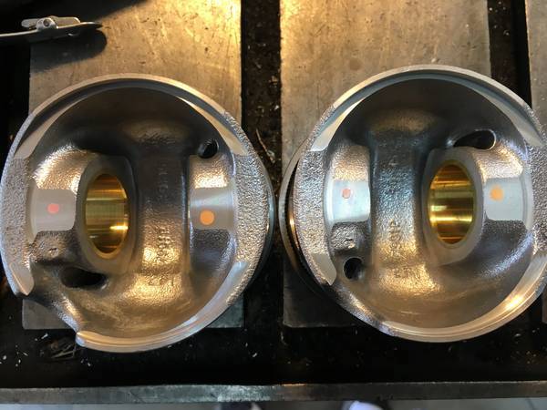
2) The original pistons on all of the 1Z/ AHU/ ALH and a few of the PD motors are not galley cooled pistons. this means the oil squirt simply sprays the bottom of the 'dome head' piston. The oil squirt is aimed "UP". The oil squirt must be redirected into the oil hole closest the the 'dog house' cutout in the bottom of the piston, as shown in the pistons below.
This is pair of 79.5mm pistons intended for a large variety of TDI engines. We specifically use these pistons with our beveled connecting rods for all 1.9 liter engines, except the AAZ or it's counterparts. The picture for the Left piston is a little deceiving, as the angle makes the oil squirt hole appear quite large, but the Right piston shows the perspective that the oil squirt would be aimed from. The hole is quite a small target.
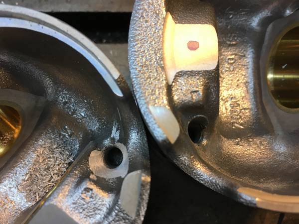
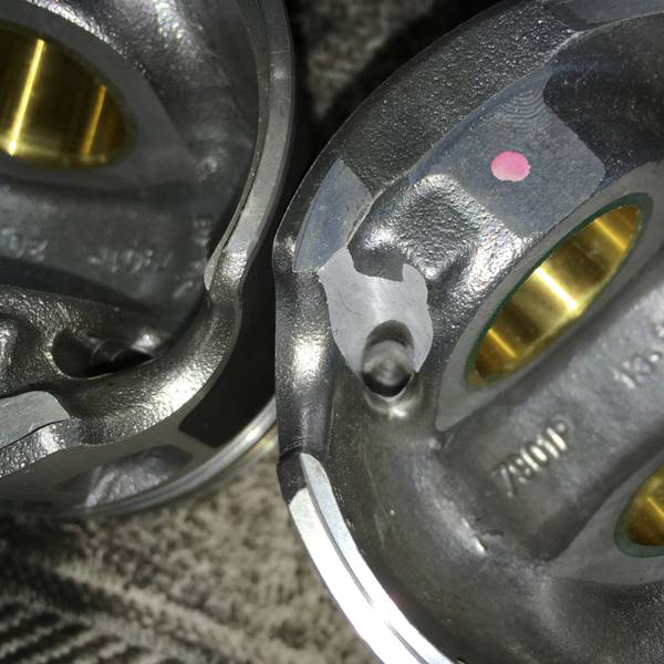
Here are a piston set showing Before/ After picture where we have made the approach to the galley hole into a funnel.
Before
After
Our purpose is to make the oil squirt pour oil directly into the galley hole from the bottom of the piston stroke, clear to the top. We weighed the amount of metal removed from creating the funnel (you can see the amount of metal removed in the piston) and it amounts to about .2 grams avg. Without producing this change, there is a rather sharp shoulder that can splash cooling oil away from the intended target, which effectively compromises the cooling ability of the oil galley. The funnel makes the approach easier to hit.
3) The issue of redirecting the oil squirt is important. It is the first thing we do when reassembling the block, as there is nothing in the way to keep us from properly positioning the oil squirt. We have a template of the piston made of cardboard, marked for wrist pin direction and galley hole position. We make matching 'wrist pin direction' marks in the bottom and top of the cylinder bore. After installing the template at the bottom of the stroke, the oil squirt is then bent and positioned to hit the center of the template mark for the galley hole. We then remove the template and install a jobber length #42 drill (or you can use similar sized drill rod) into the oil squirt and move the template to the top of the bore. Without changing the the axis position of the oil squirt at the bottom of the hole, we redirect the angle of the oil squirt, so the oil will hit the targeted oil galley hole. It is a bit tricky and that is why we funnel the piston's galley hole, to allow a bit of 'allowance and error correction'.
I realize there is a lot of dynamics, with pistons and rods flying around at a high rate of speed. The goal is to get as much oil into the target as possible. Taking some pains to make it happen will help the overall cooling of the pistons.
Bigger is better from a cooling standpoint as long as you have sufficient oil pump flow to squirt the oil far enough when it's hot while also supplying everything else with sufficient quantities of oil.
The 0.076" one will flow ~2.3 LPM @ 2 Bar oil pressure
The 0.096" one will flow ~3.7 LPM @ 2 Bar oil pressure or, to flip it around since the oil pumps are fixed flow, not fixed pressure...
The 0.096" one will have 0.79 Bar pressure at the same ~2.3 LPM flow rate.
Franko6
If indeed, the oil squirts crack at that low pressure, then I think it very wise to increase pump flow at low rpm. 4 nozzles blowing oil through a 2.8mm hole becomes quite a volume for idle pressure and I think that could further diminish oil pressure.
My further thoughts are that the older 1Z/ AHU, which also have oil squirts, and the more typical gear drive oil pump will suffer very low oil pressure at idle, if this crack pressure you have come up with, is accurate. That has been a concern for the older engines and we have found aftermarket AHU pumps weak to the point of being ineffective at idle. The bigger point for the AHU's is extremely low oil pressure at idle, for which the oil squirts could be a contributing factor.
On a side-note, we recently found that the 1.8 gasser crowd, which also has the same block arrangement as the AHU in engines like the AEB, AWW, AWD, etc., 20-valve should also be concerned for oil pressure and intermediate shaft bearing longevity. There is a group that is using a similar techinque we use on PD's to cut a radial slot in the intermediate cam bearings to make it oil better. We like it and think it is applicable to the AHU's.


